- Joined
- Feb 5, 2015
- Messages
- 662
My shop hasn’t grown too much in recent years except for the acquisition of a well-used 1944 Sheldon EXL-56B lathe. There was a LOT of shop re-shuffling required to accommodate this lathe (and a Harley-Davidson acquired at about the same time).
I’ve done little to the Sheldon except minor adjustments and parts replacement but perhaps some of these will be of interest. I have no intention of disassembling and painting this machine, BTW. It has well-earned battle scars and displaying them doesn’t trouble me at all, LOL. (The chip pan has a shallow layer of kitty litter to absorb some of the messy lube and cutting oil that eventually ends up there.)
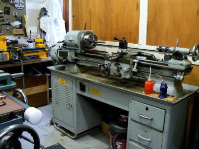
The previous owner complained about a lack of power, stating that the lathe was OK for wood and plastic. The reputation of Sheldon lathes has always been good, or that is what I’ve read, so I couldn’t understand that.
The general opinion, it seems, is that they are a step up from South Bend and Logan machines of comparable size and cost. I’ve operated both of those representative lathes and I can’t definitively state that the Sheldon is superior, although it is heavier, FWIW.
When I received the machine I noted some minor adjustment deficiencies in the under-cabinet drive. This system, by the way, is a beauty to behold for anyone that admires well-designed mechanisms. (I operated a “heavy ten” South Bend around 1967. It had a similar drive system and I admired it too.)
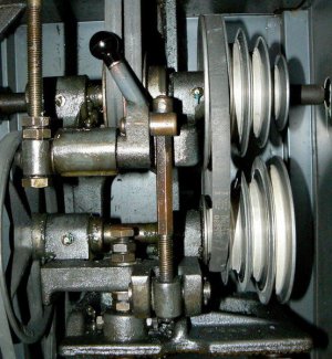
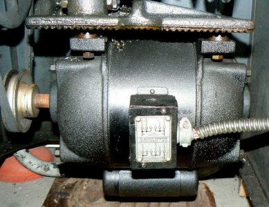
After performing some slight adjustments to the drive system and comprehensively lubricating the entire machine, which takes a while, I found the original ¾ HP motor to be adequate although marginal.
Something around 1-1/2 horsepower would have been my preference. But I can definitely live with this motor since I don’t have to make a living with it. The old motor is representative of the era when form was almost as important as function.
There was chatter when taking a DOC in steel greater than about .030, which greatly surprised me for a lathe of this size. In the original photo in this post, a small Emco 8 x 18 lathe can be seen in the background. This little lathe can and does take DOC of .250 inches with a feed of .007 in steel. This can be seen in the following thread:
http://www.hobby-machinist.com/threads/making-a-high-performance-yo-yo-what.32255/#post-272997
I thought that the Sheldon, however limited by the ¾ HP motor, should be capable of a MUCH heavier DOC than .030 !
This may have been the basis of the original owner’s comment. I joined a forum specifically for Sheldon lathes and obtained a recommended procedure for adjusting the Timken tapered roller bearings guiding the lathe spindle.
The adjustment is simple, consisting of backing off a set screw that locks the adjustment nut at the rear of the headstock, securing the adjustment nut from rotating then turning/torquing the spindle the desired amount.
There is usually no specified torque value, by the way, most lathe manufacturers seem to suggest adjustment by the “feel” of the spindle rotation or the temperature rise of the front headstock bearing.
I adjusted mine using a combination of the two methods. The photo depicts a temperature measurement of the front spindle bearing with the spindle operating at maximum RPM.
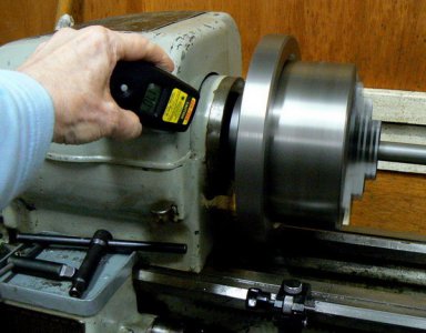
An inexpensive infra-red temperature sensor was used to measure the temperature rise after running the lathe (without a load) for fifteen minutes at the highest spindle speed. The maximum rise at that point was twenty-two degrees Celsius, which sounded good to me.
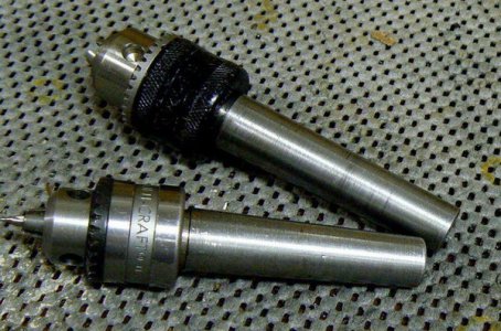
Since that adjustment, the old Sheldon has been used often, turning materials from aluminum to pre-hardened 4140 steel. The taper attachment was used to make two MT-2 tailstock arbors. These are not pretty but they are functional – they are made from 1018 steel which is always a PITA when a nice surface finish is desired.
Initially the gear train was extremely noisy and some internet research indicated that this is a common Sheldon complaint. In back gear, the noise is particularly irritating and reasonable adjustment alleviated the noise only marginally.
I have some thoughts about quieting the back gears at a future date but for now I can live with the noise. I did find that motorcycle chain lube did a better job than oil at quieting the gears. I just happened to have this lubricant so I can’t say that it’s any better than conventional open gear lube.
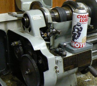
The feed/threading gear train at the left of the headstock was more amenable to noise reduction although adjustment of the center distance between some of the gears was slightly sensitive. Way lubricant and spindle lubricant didn’t quiet these gears as effectively as the same chain lube used on the back gears.
The cross-slide was sloppy and the gib adjustment was bottomed out. I disassembled the cross slide and cleaned the cast-iron gib scrupulously. I made a .030 brass shim to fit the dimensions of the side of the (trapezoidal, BTW) gib that bears against the stationary side of the cross-slide.
After cleaning and intentionally roughing the surface of the shim, it was epoxied to the gib with “JB Weld”. (I’m not suggesting that this was the best product for the application, I just happened to have it on hand.)
I wish that I’d photographed this entire process because it is a useful means to get a lot more life out of an old cast iron gib. The brass shim is just barely visible on the right side of the gib. NOTE: as previously mentioned the brass shim is stationary – it doesn’t bear against the cross slide and wear from movement.
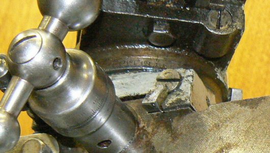
This modification allowed backing off the gib adjustment screw to allow a reasonable amount of adjustment. Precise adjustment was now possible, reducing chatter.
However, even allowing for the age and hard usage of this old girl, the backlash in the cross-slide was somewhat excessive at one half of a turn. This didn’t impair the accuracy the lathe was capable of achieving but I didn’t really care for the “slop” in the handwheel, LOL.
Again disassembling the cross-slide, I slotted the cast-iron nut that engaged the cross-slide lead screw and squeezed it in my bench vise to compress and reduce the internal diameter of the nut threads. Putting it all together again, I liked the reduction in backlash but I was hungry for more !
I disassembled the cross-slide again and widened the slot in the lead screw nut. I put the nut back in the bench vise to squeeze it just a little bit more and …… uh-oh
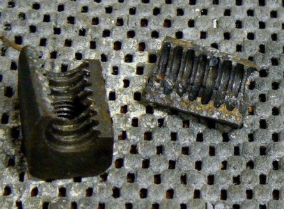
I had no desire to attempt cutting a left hand ½-8 Acme internal thread – imagine how tiny the cutting tool must be and how many cuts would be required because of its fragility ! eBay, to my shock, offered a new nut for old Sheldons. Not cheap by any means but any port in a storm, right ?
I bought it for a fixed price, no bidding was permitted. The body was oversize which was very good because I could mill it (two or three tries, LOL) until it fit comfortably under the cover of the cross-slide. BUT of course it didn’t fit the cross-slide lead screw.
E-mailed the guy who made the nuts and he noted that he also made the lead screws. I bought one of his lead screws – not cheap but everything fit, sort of. There was still more backlash than I thought appropriate for new nut and screw. I slotted the nut, as I’d done with the original part and squeezed it in the vise. NICE ….. less than .005 backlash.
OK, all is going too well, right ? Right. When putting the whole thing back together (by this time some six weeks had passed since I first disassembled the cross-side) the new lead screw didn’t look much like old one and didn’t really fit. E-mailed the guy who made the nut and the lead screw and he told me that the lead screw was really a two-piece assembly.
I looked at the old lead screw carefully and could find no signs of a joint. After e-mailing the expert again he made an excellent suggestion: cold-blue the area (he told me which area) and look for the signs of a dowel. Bingo !
The dowel pin had been polished to blend with the unthreaded diameter of the lead screw. After driving the pin out and drilling the new lead screw, inserting the old unthreaded shaft and pinning the two parts together, all was well !
Next problem: the tailstock ram screw was very tight. I don’t know how this happened but the screw was slightly bent ! I won’t go into detail but eventually I straightened the screw and the tailstock was usable EXCEPT that it drooped about .010 from the center line of the headstock.
After spending a coupla’ hours with a DTI and various thicknesses of shim stock, I reached a satisfactory compromise by inserting a shim under the far side of the front of the tailstock. For now it is held in place only by tailstock pressure.
The final plan is to insert a shim of appropriate thickness and location between the tailstock and the tailstock base. Although the shim will be securely locked in place, it can still be removed for re-adjustment of the tailstock in the future when required. Not the best fix but good enough for me.
So far, so good. Next I measured the wear on the ways to be about .015 near the headstock, not unexpected for a machine of this age. That’s a workable amount of wear for achieving precision. Workpiece diameters over about 1.0 inch will have less than .0005 diametrical error (calculated) and as the work diameter increases, the error becomes even less.
For example, a work diameter of 3.0 inches will have a calculated error that is undetectable with normal measurement instruments. Smaller diameters may require some “work around” if the application is unusally critical.
This might include turning the work slightly oversize and then filing/sanding to finish diameter. However even diameters as small as .5 inches will have a calculated error of less than .001. That’s plenty close enough for most purposes.
The carriage lead screw was remarkably unworn (as was the gear train) except for one gear. But there was quite a bit of movement when the threading lever was engaged and the carriage moved back and forth.
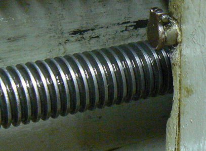
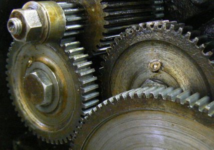
At some point, the half nuts will require refurbishment. There are a couple of ideas suggested on the internet that I may try …
In general, I’m content with this machine despite the fact that I paid more for it than one might think reasonable. However, I got free delivery from the previous owner who made a six hour round trip to bring the lathe. And I made a new friend, too.
Other than adjusting the motor drive, the lathe was completely usable at the time I received it. I’ll probably continue to tinker with it to fine-tune it functionally but I won’t pretty it up, as I stated at the beginning of this post.
I’ve done little to the Sheldon except minor adjustments and parts replacement but perhaps some of these will be of interest. I have no intention of disassembling and painting this machine, BTW. It has well-earned battle scars and displaying them doesn’t trouble me at all, LOL. (The chip pan has a shallow layer of kitty litter to absorb some of the messy lube and cutting oil that eventually ends up there.)

The previous owner complained about a lack of power, stating that the lathe was OK for wood and plastic. The reputation of Sheldon lathes has always been good, or that is what I’ve read, so I couldn’t understand that.
The general opinion, it seems, is that they are a step up from South Bend and Logan machines of comparable size and cost. I’ve operated both of those representative lathes and I can’t definitively state that the Sheldon is superior, although it is heavier, FWIW.
When I received the machine I noted some minor adjustment deficiencies in the under-cabinet drive. This system, by the way, is a beauty to behold for anyone that admires well-designed mechanisms. (I operated a “heavy ten” South Bend around 1967. It had a similar drive system and I admired it too.)

After performing some slight adjustments to the drive system and comprehensively lubricating the entire machine, which takes a while, I found the original ¾ HP motor to be adequate although marginal.
Something around 1-1/2 horsepower would have been my preference. But I can definitely live with this motor since I don’t have to make a living with it. The old motor is representative of the era when form was almost as important as function.

There was chatter when taking a DOC in steel greater than about .030, which greatly surprised me for a lathe of this size. In the original photo in this post, a small Emco 8 x 18 lathe can be seen in the background. This little lathe can and does take DOC of .250 inches with a feed of .007 in steel. This can be seen in the following thread:
http://www.hobby-machinist.com/threads/making-a-high-performance-yo-yo-what.32255/#post-272997
I thought that the Sheldon, however limited by the ¾ HP motor, should be capable of a MUCH heavier DOC than .030 !
This may have been the basis of the original owner’s comment. I joined a forum specifically for Sheldon lathes and obtained a recommended procedure for adjusting the Timken tapered roller bearings guiding the lathe spindle.
The adjustment is simple, consisting of backing off a set screw that locks the adjustment nut at the rear of the headstock, securing the adjustment nut from rotating then turning/torquing the spindle the desired amount.
There is usually no specified torque value, by the way, most lathe manufacturers seem to suggest adjustment by the “feel” of the spindle rotation or the temperature rise of the front headstock bearing.
I adjusted mine using a combination of the two methods. The photo depicts a temperature measurement of the front spindle bearing with the spindle operating at maximum RPM.

An inexpensive infra-red temperature sensor was used to measure the temperature rise after running the lathe (without a load) for fifteen minutes at the highest spindle speed. The maximum rise at that point was twenty-two degrees Celsius, which sounded good to me.
Since that adjustment, the old Sheldon has been used often, turning materials from aluminum to pre-hardened 4140 steel. The taper attachment was used to make two MT-2 tailstock arbors. These are not pretty but they are functional – they are made from 1018 steel which is always a PITA when a nice surface finish is desired.

Initially the gear train was extremely noisy and some internet research indicated that this is a common Sheldon complaint. In back gear, the noise is particularly irritating and reasonable adjustment alleviated the noise only marginally.
I have some thoughts about quieting the back gears at a future date but for now I can live with the noise. I did find that motorcycle chain lube did a better job than oil at quieting the gears. I just happened to have this lubricant so I can’t say that it’s any better than conventional open gear lube.

The feed/threading gear train at the left of the headstock was more amenable to noise reduction although adjustment of the center distance between some of the gears was slightly sensitive. Way lubricant and spindle lubricant didn’t quiet these gears as effectively as the same chain lube used on the back gears.
The cross-slide was sloppy and the gib adjustment was bottomed out. I disassembled the cross slide and cleaned the cast-iron gib scrupulously. I made a .030 brass shim to fit the dimensions of the side of the (trapezoidal, BTW) gib that bears against the stationary side of the cross-slide.
After cleaning and intentionally roughing the surface of the shim, it was epoxied to the gib with “JB Weld”. (I’m not suggesting that this was the best product for the application, I just happened to have it on hand.)
I wish that I’d photographed this entire process because it is a useful means to get a lot more life out of an old cast iron gib. The brass shim is just barely visible on the right side of the gib. NOTE: as previously mentioned the brass shim is stationary – it doesn’t bear against the cross slide and wear from movement.

This modification allowed backing off the gib adjustment screw to allow a reasonable amount of adjustment. Precise adjustment was now possible, reducing chatter.
However, even allowing for the age and hard usage of this old girl, the backlash in the cross-slide was somewhat excessive at one half of a turn. This didn’t impair the accuracy the lathe was capable of achieving but I didn’t really care for the “slop” in the handwheel, LOL.
Again disassembling the cross-slide, I slotted the cast-iron nut that engaged the cross-slide lead screw and squeezed it in my bench vise to compress and reduce the internal diameter of the nut threads. Putting it all together again, I liked the reduction in backlash but I was hungry for more !
I disassembled the cross-slide again and widened the slot in the lead screw nut. I put the nut back in the bench vise to squeeze it just a little bit more and …… uh-oh

I had no desire to attempt cutting a left hand ½-8 Acme internal thread – imagine how tiny the cutting tool must be and how many cuts would be required because of its fragility ! eBay, to my shock, offered a new nut for old Sheldons. Not cheap by any means but any port in a storm, right ?
I bought it for a fixed price, no bidding was permitted. The body was oversize which was very good because I could mill it (two or three tries, LOL) until it fit comfortably under the cover of the cross-slide. BUT of course it didn’t fit the cross-slide lead screw.
E-mailed the guy who made the nuts and he noted that he also made the lead screws. I bought one of his lead screws – not cheap but everything fit, sort of. There was still more backlash than I thought appropriate for new nut and screw. I slotted the nut, as I’d done with the original part and squeezed it in the vise. NICE ….. less than .005 backlash.
OK, all is going too well, right ? Right. When putting the whole thing back together (by this time some six weeks had passed since I first disassembled the cross-side) the new lead screw didn’t look much like old one and didn’t really fit. E-mailed the guy who made the nut and the lead screw and he told me that the lead screw was really a two-piece assembly.
I looked at the old lead screw carefully and could find no signs of a joint. After e-mailing the expert again he made an excellent suggestion: cold-blue the area (he told me which area) and look for the signs of a dowel. Bingo !
The dowel pin had been polished to blend with the unthreaded diameter of the lead screw. After driving the pin out and drilling the new lead screw, inserting the old unthreaded shaft and pinning the two parts together, all was well !
Next problem: the tailstock ram screw was very tight. I don’t know how this happened but the screw was slightly bent ! I won’t go into detail but eventually I straightened the screw and the tailstock was usable EXCEPT that it drooped about .010 from the center line of the headstock.
After spending a coupla’ hours with a DTI and various thicknesses of shim stock, I reached a satisfactory compromise by inserting a shim under the far side of the front of the tailstock. For now it is held in place only by tailstock pressure.
The final plan is to insert a shim of appropriate thickness and location between the tailstock and the tailstock base. Although the shim will be securely locked in place, it can still be removed for re-adjustment of the tailstock in the future when required. Not the best fix but good enough for me.
So far, so good. Next I measured the wear on the ways to be about .015 near the headstock, not unexpected for a machine of this age. That’s a workable amount of wear for achieving precision. Workpiece diameters over about 1.0 inch will have less than .0005 diametrical error (calculated) and as the work diameter increases, the error becomes even less.
For example, a work diameter of 3.0 inches will have a calculated error that is undetectable with normal measurement instruments. Smaller diameters may require some “work around” if the application is unusally critical.
This might include turning the work slightly oversize and then filing/sanding to finish diameter. However even diameters as small as .5 inches will have a calculated error of less than .001. That’s plenty close enough for most purposes.
The carriage lead screw was remarkably unworn (as was the gear train) except for one gear. But there was quite a bit of movement when the threading lever was engaged and the carriage moved back and forth.


At some point, the half nuts will require refurbishment. There are a couple of ideas suggested on the internet that I may try …
In general, I’m content with this machine despite the fact that I paid more for it than one might think reasonable. However, I got free delivery from the previous owner who made a six hour round trip to bring the lathe. And I made a new friend, too.
Other than adjusting the motor drive, the lathe was completely usable at the time I received it. I’ll probably continue to tinker with it to fine-tune it functionally but I won’t pretty it up, as I stated at the beginning of this post.

