Next round of CNC upgrades:

Metal

Registered
Registered
Joined
Sep 30, 2015
Messages
233
Hey folks, I'm prepping for the next round of upgrades for the bridgeport retrofit.

I have the X/Y ballscrews, and just need to make a bolt circle adapter plate (probs this weekend) and we'll be rocking and rolling.

So my questions are about the additions I plan on doing while I'm at it:

1. I'm adding inductive "home" sensors and finally limit switches to the X/Y, and I've had noise issues with switches in the past, is there anything I need to specifically watch out for with inductives?

2. Probably for Jim: but if anyone has done a ballscrew-to-Z axis conversion for the quill I'd like to see it, it looks like I could gut the internals and pull the Z down by the collar around the depth gauge, so I could still use it manually sometime, but I'm not sure if that is the way to go since many conversions I've googled have that whole area inside a box its tough to see what is going on there.

3. I'm also making a big old fixture/sub plate, and am looking for any ideas to be able to place it consistently /without/ drilling and putting pins in the table. My thought was to make T nuts with females for the pins above setscrews to secure them to locate and then regular old bolts to tie it down afterwards.
 
1. I'm adding inductive "home" sensors and finally limit switches to the X/Y, and I've had noise issues with switches in the past, is there anything I need to specifically watch out for with inductives?

Wiring limit switches normally closed (NC) is the best way to eliminate noise. It also stops the machine in case of a wire break. You can get inductive proxs in a normally closed configuration also.

Just my opinion here, but I think home switches are useless on a mill. The exception is a mill equipped with a tool changer, in that case you would want one on the Z. It is also possible to make a really cheap (5 for $10 from Ebay) micro switch into precision limit switch. The one I did on the Shizuoka Z, home holds +/- 0.0001 consistently. It's how you design the actuating ramp, to get it to snap over instantly at the same spot each time.

2. Probably for Jim: but if anyone has done a ballscrew-to-Z axis conversion for the quill I'd like to see it, it looks like I could gut the internals and pull the Z down by the collar around the depth gauge, so I could still use it manually sometime, but I'm not sure if that is the way to go since many conversions I've googled have that whole area inside a box its tough to see what is going on there.

I have never done a ball screw conversion on the Z, but that is the common way of driving the quill axis. To keep some manual capability, you would want to make a new ''collar'' that would match the quill attachment end, but more of a ''T'' shape that the ball nut housing could bolt to with two bolts and a removable spacer (for clearance in manual mode). That would allow you to remove the bolts and spacer for manual operation. I thought about doing it this way with mine, but decided it would be too much trouble to remove the bolts to switch back and forth between manual and CNC. That's why I designed mine the way it is.

3. I'm also making a big old fixture/sub plate, and am looking for any ideas to be able to place it consistently /without/ drilling and putting pins in the table. My thought was to make T nuts with females for the pins above setscrews to secure them to locate and then regular old bolts to tie it down afterwards.

I would fasten it to the table with the T-nuts, using flat head screws. When making the plate, mill the back of it as the final operation to make sure that it's aligned with the X axis. Then also mill at least along the right hand side to align that with the Y axis. That way you have two sides that are square and at a known location. Then when you install it the next time, just indicate the back side and it is square. You could also put a dowel pin at a known location to use as a datum point, but not really needed, you already know where the right and back edges are.
 
Last edited:
Just a question on control system.. will this be Mach3 based or something else?
 
I have a bridgeport knee mill with a 3 axis cnc control. The control leaves a lot to be desired by todays standards( anilam crusader II) but the z axis ball screw set up might work for you. I posted an image from the net that kinda shows it. I can take some better pics of mine if you want. Might be a day or two before I can get to it got a nasty cold
$_1.JPG
 
Wiring limit switches normally closed (NC) is the best way to eliminate noise. It also stops the machine in case of a wire break. You can get inductive proxs in a normally closed configuration also.

I would fasten it to the table with the T-nuts, using flat head screws. When making the plate, mill the back of it as the final operation to make sure that it's aligned with the X axis. Then also mill at least along the right hand side to align that with the Y axis. That way you have two sides that are square and at a known location. Then when you install it the next time, just indicate the back side and it is square. You could also put a dowel pin at a known location to use as a datum point, but not really needed, you already know where the right and back edges are.

Thanks Jim
Yeah, the idea would be to fly cut all but one side, then flycut the "use" side, drill the locating holes, ect. all in one go so it all indicates to the table square and the screw holes are square to the axis since it was all done in one setup
folks were saying to make Tslot keys but I really don't see those as being very accurate on a like 3 foot long chunk of aluminium.
I'm going to just start with 1/4-20 tapped holes but if they start stripping I can always redrill them bigger and use threaded inserts or something. I got the chunk for free and it'll only cover about 2/3rds of the table's Y so I'm doing what I can with what I got.


Just a question on control system.. will this be Mach3 based or something else?
It already runs, and it mach3 based, It wasn't overly difficult once I figured out the servo driver gremlins (read: gecko drivers suck)


I have a bridgeport knee mill with a 3 axis cnc control. The control leaves a lot to be desired by todays standards( anilam crusader II) but the z axis ball screw set up might work for you. I posted an image from the net that kinda shows it. I can take some better pics of mine if you want. Might be a day or two before I can get to it got a nasty cold
View attachment 232250

If you could, yeah

I'm most interested in how the parts itself attach to the milling head, I can make a motor mount and ballscrew axis no problem, but attaching it to the head seems to be some black magic involved, since "I" would just use slightly longer quill head bolts but it looks like the ones ive seen use some kind of funky brackets that somehow attach to the quill screw or the head itself
 
My Tormach has a brake on the z axis that engages whenever the motor is powered down to prevent the head slipping down when the mill not powered.

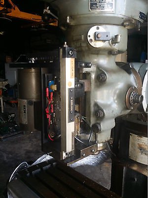
I installed optical homing on the machine and consistently repeat to +/- .0001 as well. I did a post on the CNC Zone forum about the build. I left my OEM mechanical limit switches in place in the event of a failure in my primary homing system. The OEM limit switch also controls the far end limit.

I use Path Pilot for my controller and it requires that the machined be homed before it can be used. One nice feature in PathPilot is that it then sets soft limits for the three axes and you can run G0 to the soft limit and never hit the hard limit switch.
 
It is also possible to make a really cheap (5 for $10 from Ebay) micro switch into precision limit switch. The one I did on the Shizuoka Z home holds +/- 0.0001 consistently. It's how you design the actuating ramp, to get it to snap over instantly at the same spot each time.
Jim, I'd like to see your modification to improve positional sensitivity with microswitches if you don't consider it a trade secret.
 
Jim, I'd like to see your modification to improve positional sensitivity with microswitches if you don't consider it a trade secret.

Not a trade secret at all, I'll have to draw it up. I just fit it with the grind/file, test method. I'll post a thread when I get a chance.
 
Short update: ballscrews are in, Y axis is buttery smooth but the X has a reasonable amount of resistance to it, so I think the adapter plate I had to make for the screws is a scoonch off, going to remachine it this weekend.

question: if I try to move the ballscrews with the table locks on, the screw will rotate a little, then "spring" back to its original location, I'm guessing that is the load being absorbed by all the individual balls but, it doesn't seem right, is it?
 
question: if I try to move the ballscrews with the table locks on, the screw will rotate a little, then "spring" back to its original location, I'm guessing that is the load being absorbed by all the individual balls but, it doesn't seem right, is it?

That seems somewhat reasonable. If the table is not able to move and you apply pressure to the ballscrew something has to give if you are stronger than the screw. Everything has some elasticity, so I think what you are seeing is just some wind up in all of the components together.
 
Back
Top