
-
Welcome back Guest! Did you know you can mentor other members here at H-M? If not, please check out our Relaunch of Hobby Machinist Mentoring Program!
You are using an out of date browser. It may not display this or other websites correctly.
You should upgrade or use an alternative browser.
You should upgrade or use an alternative browser.
New VFD
- Thread starter murraym
- Start date
- Joined
- Jan 1, 2018
- Messages
- 1,291
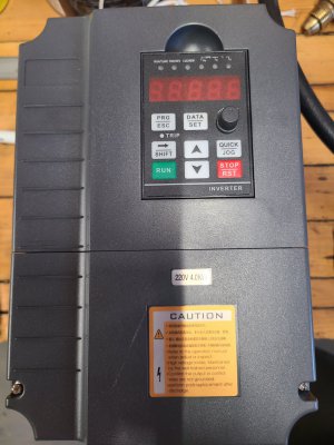
Bottom line, that VFD is based on one of the massed produced VFD control/driver chips and will be fine for running a 3 phase motor on a 1 phase power source.
There are 3 terminals for AC power input on that VFD. For single phase input you will only be using 2 of the 3 terminals. The 3rd terminal will be left unused with no wire being attached to the terminal.
40 years ago VFD's were designed and used mainly for providing speed control for 3 phase motors on 3 phase power sources. These days most all VFD's are designed with the purpose of running 3 phase motors on 1 phase power as a primary function.
The first thing a VFD does is convert AC power to DC. On a 1 phase input this is done with a 4 diode rectifier. On a 3 phase input it is done with a 6 diode rectifier. The beauty of a 3 phase rectifier is you can neglect to power 2 of the diodes and it works perfectly for single phase rectification with a little rougher DC output. After the rectifier power transistors (IGBT's, Mosfets) turn on and off creating AC wave forms on each of the 3 phase legs. There are a couple of manufactures that make VFD control / Power transistor driver chips. Most all of the various inexpensive VFD's are based on these few chips. High end VFD's usually have much more functionality meaning much more complex control / driver IC's. A lot of the extra cost of the high end VFD's are due to the R&D cost of the fancy control chips which are amortized over a much smaller number of VFD's produced. Mass produced VFD control/driver IC's almost always have a sample circuit in their documentation describing a basic implementation of the IC. This greatly reduces the R&D costs for Chinese manufactures of inexpensive VFD's.
My first VFD, about 25 years ago, was a used surplused Allen Bradley 3hp VFD. It was HUGE! The power components weren't all that big but the control board had tons of discrete components on it which is what made it so big. It had a circuit to detect incoming 3 phase power and shut down if one of the legs were missing. I was able to get around this by jumpering the second single phase input power wire to the third input power terminal. The controller recognized input power on all three legs and ran properly without throwing an error.
Last edited:
So this all makes sense to me. A quick follow up question for you. Would it make sense to put a jumper between phases a and c? My thought is it would help with the"dirty" DC buss. The rectifier should then be generating DC between phases A&B , B&C and not A&C. does that make sense?
Thank you again for your thoughts.
Thank you again for your thoughts.
- Joined
- Apr 30, 2015
- Messages
- 11,817
No, all that would do is put two of the diode legs in parallel. Wouldn't change the rectification. Would increase the current handling
capability of that side of the bridge but you still have one leg standing by itself. No real benefit.
capability of that side of the bridge but you still have one leg standing by itself. No real benefit.
Last edited:
- Joined
- Feb 2, 2013
- Messages
- 3,820
I have tested similar vfd’s
There is no need to add any jumpers to the input terminals.
The R and S terminals are the single phase input terminals
There is no need to add any jumpers to the input terminals.
The R and S terminals are the single phase input terminals
- Joined
- Jan 1, 2018
- Messages
- 1,291
So this all makes sense to me. A quick follow up question for you. Would it make sense to put a jumper between phases a and c? My thought is it would help with the"dirty" DC buss. The rectifier should then be generating DC between phases A&B , B&C and not A&C. does that make sense?
Thank you again for your thoughts.
Nope. Each leg of 3 phase current is offset by 120 degrees so they fill in the gaps better when rectified to DC. This is not the case with single phase. Jumpering the extra leg will have no effect on how smooth the rectified DC current will be. Capacitors are used to smooth out the ripple in rectified DC. That VFD will have any capacitors necessary to smooth rectified single phase properly for the application.

The 3 legs of 3 phase current are 120 degrees apart:

Last edited: