- Joined
- Jan 20, 2016
- Messages
- 1,011
I've just completed the installation of a DRO for my 12x36 Central Machinery lathe.
I was concerned about covering the carriage oilers and lock with a DRO. But Dan at DRO PROs suggested a new system that they just got in. It is not much more expensive than glass scales and cheaper than many other magnetic scales I've seen.
The system uses Electronica “Magna Slim Scales” (magnetic) and EMC14A reader heads (all IP67 contaminate proof) and a Ditron D80 LCD display. I believe the scales are fairly new industry wide. I got 5 micron (0.0002”) resolution on both axis.
The read head is tiny at 36mm (1.417”) x 13mm (0.511”) x 14mm (0.551”). The scales are a lot smaller than standard magnetic scales measuring 15mm (0.590”) high and 7.2mm (0.283”) thick with their protective covers. The scale can be read from end to end and does not need additional space for end caps. To be able to read, say, a max of 6” you only need room for 6” total. Not 6” plus 2, 3 or 4 inches of unusable/unreadable end caps or safety margins. The mounting screws are underneath the scale.
I would think that the small size and being able to read the entire length of the scale would make them especially attractive to users with smaller (and mini) machines and other space limited installations.
Note that in my installation I used the entire length of the scales as shipped.
Since they will not interfere with anything at this length I couldn't see any advantage in cutting them.
Explanation of the pictures is in the order that they appear;
#1: Here, the center extrusion is temporally held in the approximate position with double sided tape. On final assembly this center part “floats” between the 2 fixed end pieces (no tape or mounting screws). One end piece with mounting holes is laying to the left.
#2: The left end piece in place (the illusion of it being crooked is caused by camera angle). Once both end pieces are installed, leveled and inline with each other the center part just “floats” between them – held by the scale's stainless backing. The screw in the bottom center of the end piece (you can just about see the head) eventually tightens down on the strip to keep it from moving.
#3: A drawing of an end piece. The scale is flexible like a refrigerator magnet and molded to a thin strip of stainless steel that is just wider than the magnetic strip. The stainless strip slides into the slot of one end piece, through the slot in the center section and into the slot of the end piece on the other side.
#4: End pieces, center extrusion and magnetic strip scale in place. The protective stainless steel stick-on cover is not in place yet. Notice that I will still be able to get to my oilers and carriage lock (the hole towards the back of the picture). The oilers would have been inaccessible with standard magnetic or glass scales and the carriage lock too close for comfort.
#5: The read head and protective strip in place. The gap between the ends and center extrusions is called for in the instructions. DRO PROs don't have new hardware for this system yet so they sent the stuff from the standard sized system. The standard read head would have taken up that entire top surface of the black mounting block. I could have milled the block to fit the read head and made it much smaller (and I still may sometime) but it shouldn't cause problems as it is.
#6: Todd (DRO PROs) said just to shim the end pieces to get everything in line. I found one spot on the lathe casting that was especially high (the casting is wavy). So I decided to hit it with a flapper disc and take the high spot down a little. I discovered that the entire base casting is covered with a thin layer of automotive body putty!
#7: One of my first paying jobs (other than sweeping the floors) was at my dad's Chevy dealership's body shop (where I quickly learned that there is no such thing as body work – there is just sanding). So it just kind of evolved from that first little high spot that I flattened the whole scale path by sanding rather than shim the ends. I got the entire path within +0.01mm -0.08mm and one little shim on the left end. The only way I know how to sand is like you would a car and feather-edge it, so that is why the sanded area is so wide.
#8: The Z axis read head and stainless steel protective strip in place. Again, the read head mounting hardware is much bigger than needed. Maybe some day I will paint the sanded area (all body putty – no bare metal) and mill down the hardware. Maybe. Someday.
#9: Everything tested and in place. Just running the wiring cables. I'm told that between the IP67 water resistance rating, being almost totally enclosed by the extrusion and the front protective stainless strip that there is no need for a protective cover. When I first learned of no protective covers and of floating centers I was sure I would be making some design changes. However, now that I see it first hand I am a lot more comfortable. It is much more robust than you would think and I doubt I will need or want to make those additions.
#10: The lathe is back together and ready to run. Except for a new drive belt that I ordered locally, was told (after a supposed phone call to somewhere to confirm stock) it would be here the next day. That was last week. Friday they said it should be here next week. And, they will probably want full retail plus shipping when it finally does get here. They won't get it!
#11: The Ditron display. There are 4 icon menu bars available (bottom of the LCD) that can be rotated through with the up/down arrow keys . The F buttons access the different features (icons) of whichever menu bar is displayed above them. The pertinent section of the owners manual (in real English) is available within each menu item as help screens.
All in all is seems like a good system. I'm happy with the purchase, the price and especially with the help I've gotten and ease of dealing with DRO PROs. Of course the real proof will be when I start using it (need that belt). I'll keep this post updated.
#1 #2
#2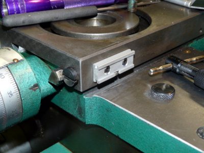 #3
#3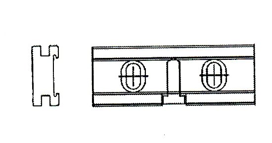
#4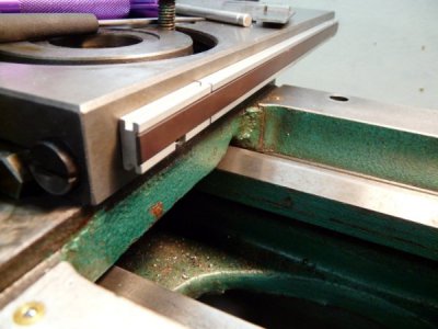 #5
#5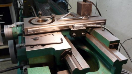 #6
#6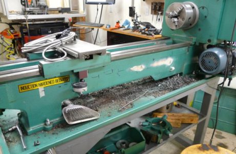
#7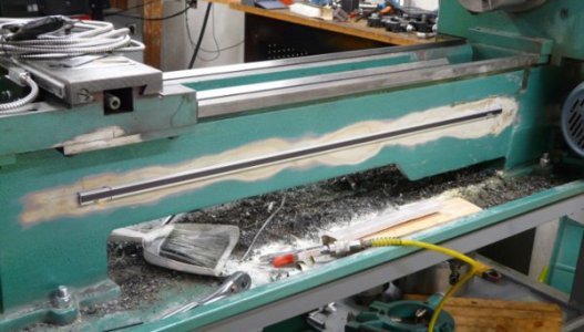 #8
#8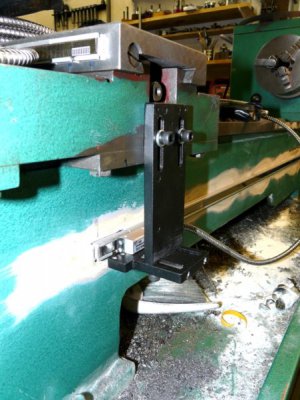 #9
#9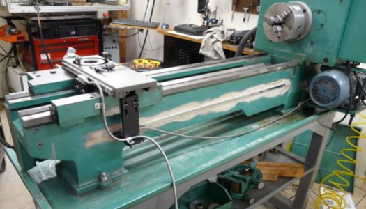
#10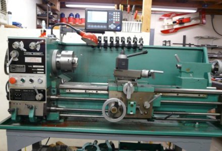
#11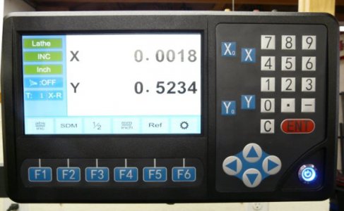
I was concerned about covering the carriage oilers and lock with a DRO. But Dan at DRO PROs suggested a new system that they just got in. It is not much more expensive than glass scales and cheaper than many other magnetic scales I've seen.
The system uses Electronica “Magna Slim Scales” (magnetic) and EMC14A reader heads (all IP67 contaminate proof) and a Ditron D80 LCD display. I believe the scales are fairly new industry wide. I got 5 micron (0.0002”) resolution on both axis.
The read head is tiny at 36mm (1.417”) x 13mm (0.511”) x 14mm (0.551”). The scales are a lot smaller than standard magnetic scales measuring 15mm (0.590”) high and 7.2mm (0.283”) thick with their protective covers. The scale can be read from end to end and does not need additional space for end caps. To be able to read, say, a max of 6” you only need room for 6” total. Not 6” plus 2, 3 or 4 inches of unusable/unreadable end caps or safety margins. The mounting screws are underneath the scale.
I would think that the small size and being able to read the entire length of the scale would make them especially attractive to users with smaller (and mini) machines and other space limited installations.
Note that in my installation I used the entire length of the scales as shipped.
Since they will not interfere with anything at this length I couldn't see any advantage in cutting them.
Explanation of the pictures is in the order that they appear;
#1: Here, the center extrusion is temporally held in the approximate position with double sided tape. On final assembly this center part “floats” between the 2 fixed end pieces (no tape or mounting screws). One end piece with mounting holes is laying to the left.
#2: The left end piece in place (the illusion of it being crooked is caused by camera angle). Once both end pieces are installed, leveled and inline with each other the center part just “floats” between them – held by the scale's stainless backing. The screw in the bottom center of the end piece (you can just about see the head) eventually tightens down on the strip to keep it from moving.
#3: A drawing of an end piece. The scale is flexible like a refrigerator magnet and molded to a thin strip of stainless steel that is just wider than the magnetic strip. The stainless strip slides into the slot of one end piece, through the slot in the center section and into the slot of the end piece on the other side.
#4: End pieces, center extrusion and magnetic strip scale in place. The protective stainless steel stick-on cover is not in place yet. Notice that I will still be able to get to my oilers and carriage lock (the hole towards the back of the picture). The oilers would have been inaccessible with standard magnetic or glass scales and the carriage lock too close for comfort.
#5: The read head and protective strip in place. The gap between the ends and center extrusions is called for in the instructions. DRO PROs don't have new hardware for this system yet so they sent the stuff from the standard sized system. The standard read head would have taken up that entire top surface of the black mounting block. I could have milled the block to fit the read head and made it much smaller (and I still may sometime) but it shouldn't cause problems as it is.
#6: Todd (DRO PROs) said just to shim the end pieces to get everything in line. I found one spot on the lathe casting that was especially high (the casting is wavy). So I decided to hit it with a flapper disc and take the high spot down a little. I discovered that the entire base casting is covered with a thin layer of automotive body putty!
#7: One of my first paying jobs (other than sweeping the floors) was at my dad's Chevy dealership's body shop (where I quickly learned that there is no such thing as body work – there is just sanding). So it just kind of evolved from that first little high spot that I flattened the whole scale path by sanding rather than shim the ends. I got the entire path within +0.01mm -0.08mm and one little shim on the left end. The only way I know how to sand is like you would a car and feather-edge it, so that is why the sanded area is so wide.
#8: The Z axis read head and stainless steel protective strip in place. Again, the read head mounting hardware is much bigger than needed. Maybe some day I will paint the sanded area (all body putty – no bare metal) and mill down the hardware. Maybe. Someday.
#9: Everything tested and in place. Just running the wiring cables. I'm told that between the IP67 water resistance rating, being almost totally enclosed by the extrusion and the front protective stainless strip that there is no need for a protective cover. When I first learned of no protective covers and of floating centers I was sure I would be making some design changes. However, now that I see it first hand I am a lot more comfortable. It is much more robust than you would think and I doubt I will need or want to make those additions.
#10: The lathe is back together and ready to run. Except for a new drive belt that I ordered locally, was told (after a supposed phone call to somewhere to confirm stock) it would be here the next day. That was last week. Friday they said it should be here next week. And, they will probably want full retail plus shipping when it finally does get here. They won't get it!
#11: The Ditron display. There are 4 icon menu bars available (bottom of the LCD) that can be rotated through with the up/down arrow keys . The F buttons access the different features (icons) of whichever menu bar is displayed above them. The pertinent section of the owners manual (in real English) is available within each menu item as help screens.
All in all is seems like a good system. I'm happy with the purchase, the price and especially with the help I've gotten and ease of dealing with DRO PROs. Of course the real proof will be when I start using it (need that belt). I'll keep this post updated.
#1
 #2
#2 #3
#3
#4
 #5
#5 #6
#6
#7
 #8
#8 #9
#9
#10

#11

Last edited:
