New PM1440GT & WJ200 VFD

Scott-ak

Registered
Registered
Joined
Nov 14, 2020
Messages
42
First, thank you admins for maintaining the forum!

Second, mksj, you are a rockstar! The technical info you have posted on this site is gold. That you share it for free shows a depth of character very rarely seen these days. I wish you were closer because I would gladly pay to have you set up my new machine & vfd! It's not that I can't, I worked in oil & gas process control 30 years ago, I'm tired and looking for life's easy button. What mental energy I have I'd prefer to spend on making chips, not relearning electronics & controls.

I have been looking at and reading everything I can find in order to power up this new lathe. It's the 3 phase, 3HP model and the vfd is the 22SF. My shop is single phase. My goal is to retain the lathes factory functions and switches as they come from PM. I am not looking to add additional external controls or features. I have read so much that my head is drowning.

I know there isn't a one size fits all and the closet I can find is mksj's post from December 26, 2017 (the day after Christmas!). I will continue studying the files and wonder do you have something simpler? a conversion rather than a full new build?

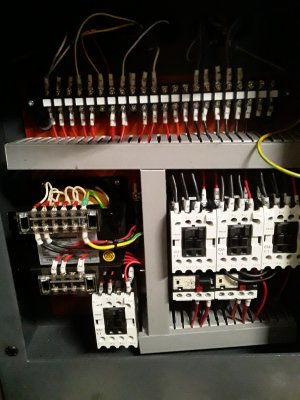
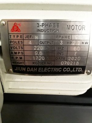
This is the new lathes control board and motor plate.
 

Attachments

  • 20201108_122222_resized.jpg
    20201108_122222_resized.jpg
    582.9 KB · Views: 130
  • 20201108_122430_resized.jpg
    20201108_122430_resized.jpg
    542.4 KB · Views: 133
A numer of us have tried to providse documents and provid guidance to share what we have learned. If you go to the end of the 1440GT basic VFD install I post the latest updated files, but also attached them here. This same basic approach can also be used on a 1440/1640TL. It doesn't get much easier than following the pictures for the wiring to get yourself up and running. You can expand on that to suit your needs. The key point to understand is that the motor is directly connected to the VFD, the VFD has low voltage inputs that controls the motor functions. By using the contactors to switch the VFD low voltage inputs, you are keeping all the safety interlocks that come with the lathe. The only tricky part is that the foot brake switch should be replaced with a dual pole, one pole is used for the existing wiring, the other pole which is a NO, sends a signal to the VFD that tells it not to brake when you are using the mechanical brake.
 

Attachments

  • VFD enclosure system recommended components for 2-3 Hp VFD 12-22-2019.pdf
    1.9 MB · Views: 1,767
  • PM1440GT Basic Wiring Changes for using the Contactors to switch the VFD inputs 23 DEC 2018.pdf
    4.8 MB · Views: 278
  • PM1440GT BASIC VFD PROGRAMMING USING THE STOCK CONTROL SYSTEM AND CONTROLS.pdf
    3.3 MB · Views: 214

Thanx mksj. Yeah that looks simple and I will head down this path. If I might ask a few questions?

1. Do you think I can wire the existing emergency stop in place of the lighted version in the notes?
2. Is it possible to retain the jog function switch or is it a no go because it's single throw? For now I'd just do without and maybe order a double throw later.
3. I thot I'd seen in one of the many pages I read that you had an example that retained the factory foot switch (I will keep looking for it).
4. This machine has a 4th contactor. It's below the transformer. I'm sure I can figure out what it's connected to when I pull all the wires from the trays but figured I'd ask if you knew off the top of your head.

Thanx again for your help!!!

Scott

BTW this would be a whole lot easier if I had left it on the pallet and put the whole thing on the bench! lol As it is I put it in it's final home about 10" from the wall and moved the other machines and benches in place blocking it in.
 
You can use the existing E-Stop, although I like to use a dual pole so one side is wired as the current one, the other side kills the commands to the VFD so that even if say a contactor stuck closed (very unlikely) the signal to the VFD is blocked. I always like to have some redundancy, but it is not required. The only reasons for the lighted E-Stop is because many people replace the stock power light hole with a speed control pot.

On Page 16 it describes the replacement brake switch and recommendation on hooking it up.

The ONLY rewiring is to remove the high voltage wiring to the forward and reverse contactors. You must leave all the other wiring and conatcotrs as is for everything to work correctly. You are not changing how anything operates, you are just using the on set of contacts on the contactor to signal the VFD direction. Yopu must also provide 240VAC to the control board to power the transformer and coolant pump. Only two of the three terminals are connected to 240VAC, these will be the ones that feed the transformer, I think usually R and S.

The Jog can be left as is, as such it operates the forward contactor so it would operate just like the stock machine (i.e. it is a full speed jog). Alternative is to use the VFD jog which is 6 Hz and much slower, a joystick jog is around $30 and allows you to jog in either direction. You can start out simple and then add/modify at a later point, but always consider safety.

No problem if you have some questions,
Mark
 
Another question :-\

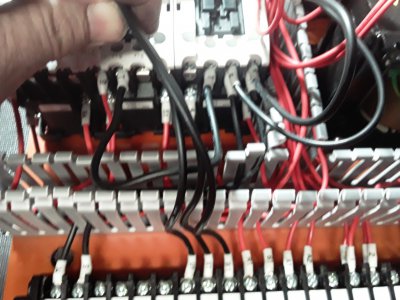
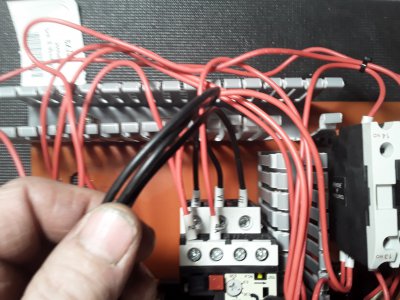
My coolant contactor has a T jumper (5 L3) connected to the forward contactor.

In your pics:

I see an unlabeled wire in the T position (5 L3) of the coolant contactor. It looks like it might be going to the coolant overload relay position 4 t2.

The coolant overload relay has U1, unlabled, V1 on posts 2, 4, 6

My coolant overload realy has U1, V1, W1 on 2, 4, 6 and they connect to the terminal bar


I am thinking I should move the W1 on my coolant overload to connect to 5 L3 on the coolant contactor.
 

Attachments

  • 20201114_170644_resized.jpg
    20201114_170644_resized.jpg
    520.9 KB · Views: 138
  • 20201114_170548_resized.jpg
    20201114_170548_resized.jpg
    546.3 KB · Views: 100
Remove the T wire it is not used. The coolant pump in newer models is single phase, should run off of R and S. L3 or T on the coolant contactor may not be used, it varies on how they are wired. You can trace back the connections from the coolant pump to see whaere they get power from.
Leave the coolant contact wire to the terminal strip.

Power in is to R and S for single phase, coolant power is V1 and U1.
lathe panel UR.JPG


Rewired baord.
Rewired panel.jpg
 
Mark, I got the high power side of things going yesterday, lathe spins, 24v light, 120v acc and the coolant pump operates, thank you. I'm on to the control side today. Mostly just studying cause I don't have any shielded wire handy. I think I'll put the safety switches, emergency stop, foot sw and cover sw, all in series between P24 and the fwd/rev contactors. That should get it up and running while I consider other things like breaking resistor, two way jog, etc.
 
Braking resistor should not be done later, they are really a requirement on a lathe because of the momentum in the system. If you try to brake too fast or have a heavy object in the chuck the lathe will go into an over voltage error with no braking which is dangerous. A braking resistor is inexpensive, Mouser or Allied electronics should ship to your location, they are around $50, order it along with the foot brake switch. Shielded cable is not a requirement, but recommended if available. The important point is do not tie the motor cable to the control cables, they can cross but otherwise try to keep them 4-6" apart when running them in parallel. The foot brake should be wired per the diagram provided, it is already wired through the machine E-Stop 24VAC to break power to the power reset relay, the other pole issues a free run.

There should be no 120VAC, only 24VAC for the contactors/relays/light and 240VAC single phase. Also there is NO neutral connection to the VFD, power in is 240VAC to terminals L1 and L3/N. It is only labeled N because rest of world does not use split phase so N is at ground potential relative to 240VAC.

VFD Wiring Connections.jpg
 
[QUOTE="mksj, post: 794876, member: 31851"

There should be no 120VAC, only 24VAC for the contactors/relays/light and 240VAC single phase.

thanx I'll look into the BR! I did get an E07.2 when I powered down a test run at 2000 spindle rpm. Not sure what the ".2" references but E07 is overvoltage protection. The 24vdc (light) and 120vac (acc/dro) I mention come from the transformer that's fed by the 220. sorry for that confusion

I am running control wire in separate conduit but it will cross high voltage in the vfd cabinet and lathe panel. Maybe I'll give it a try w/o shielding.
 
Back
Top