- Joined
- Feb 1, 2015
- Messages
- 9,948
I have welders in three separate locations and while I love my autodarkening helmet, I don't like dragging it from location to location. I have a collection of old Fibre Metal welding helmets that have been out of use because the steel spring clips have rusted away. I have scoured the internet, looking for replacement clips without any luck. I finally gave up and decided to have a go at making my own.
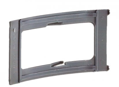
The challenge was the old clips are long gone so I really didn't have a pattern to model the replacement after, only a distant memory. The basic design of the clip is a bent spring with two tabs centrally located, top and bottom to permit the the clip to be overextended sufficiently so it can be inserted into retaining slits in the helmet. Once the clip has been seated, the two tabs will hold the filter lens in position. Here is a later version in plastic to illustrate the concept.

The distance between the retention slits is approximately 4.5". Since there is a bow in the clip the actual distance would be somewhat greater. I didn't know how much of a bow to allow but I drew up a model in SolidWorks with a 1" bow and came up with an arc length of about 5". to test the design, I cut a 2" x 5" piece of sheet metal to try. It turned out that 4.75" was a better choice. I also happily realized the it didn't have t be spring steel as the rounded shape gave substantial rigidity to clip.
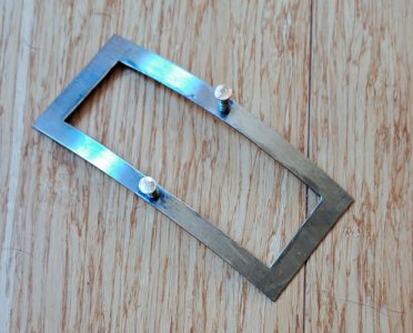
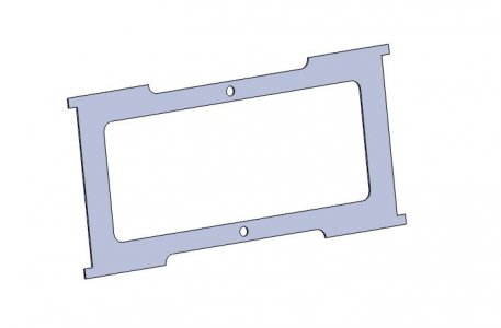
I had some .024" stainless steel and I laid the part out and cut the outside profile on my shear. To cut the opening, I used a cutoff wheel in my Dremel. I was thinking about how to cut the two tabs when I came up with the idea of using two spring loaded buttons instead. I turned two buttons out of brass and drilled two .125" holes in the clip. For the springs, I cut a spring from a ball point pen in half . I installed the springs, inserted the buttons in the holes in the clip, and peened them over to form a rivet head for retention. The clip worked as it should. I revised my SolidWorks model to reflect my experiences and when I make another clip, I will cut it out on the CNC mill instead. Here is the finished clip and the revised SolidWorks model.
Now all I have to do is remember where I put those filter lenses.

The challenge was the old clips are long gone so I really didn't have a pattern to model the replacement after, only a distant memory. The basic design of the clip is a bent spring with two tabs centrally located, top and bottom to permit the the clip to be overextended sufficiently so it can be inserted into retaining slits in the helmet. Once the clip has been seated, the two tabs will hold the filter lens in position. Here is a later version in plastic to illustrate the concept.

The distance between the retention slits is approximately 4.5". Since there is a bow in the clip the actual distance would be somewhat greater. I didn't know how much of a bow to allow but I drew up a model in SolidWorks with a 1" bow and came up with an arc length of about 5". to test the design, I cut a 2" x 5" piece of sheet metal to try. It turned out that 4.75" was a better choice. I also happily realized the it didn't have t be spring steel as the rounded shape gave substantial rigidity to clip.
I had some .024" stainless steel and I laid the part out and cut the outside profile on my shear. To cut the opening, I used a cutoff wheel in my Dremel. I was thinking about how to cut the two tabs when I came up with the idea of using two spring loaded buttons instead. I turned two buttons out of brass and drilled two .125" holes in the clip. For the springs, I cut a spring from a ball point pen in half . I installed the springs, inserted the buttons in the holes in the clip, and peened them over to form a rivet head for retention. The clip worked as it should. I revised my SolidWorks model to reflect my experiences and when I make another clip, I will cut it out on the CNC mill instead. Here is the finished clip and the revised SolidWorks model.

Now all I have to do is remember where I put those filter lenses.

