New layshaft

12bolts

Global Moderator
Registered
Joined
Apr 23, 2011
Messages
2,476
I have needed a new layshaft for sometime. At some stage in its life one of the factory original plain iron bearings had been replaced with a steel bushing, but still only running on the steel shaft. They had made provision for oiling but it always ran warm to hot.
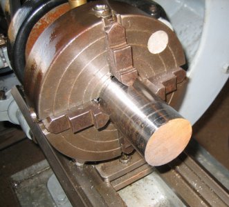
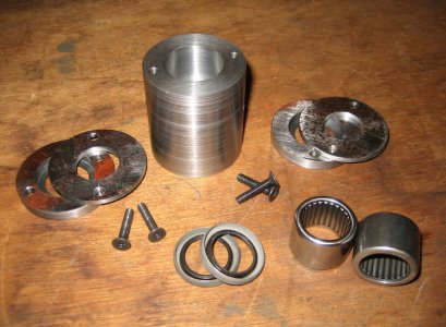
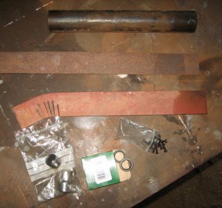
After replacing the drive motor and upping the RPM range, I thought it was time to fix the layshaft problem before something catastrophic occurred. So some 45mm dia 12L14 for bearing housings, various bits of flat bar from the scrap bin, needle rollers, oil seals and 4mm CS cap screws.
IMG_01.JPG
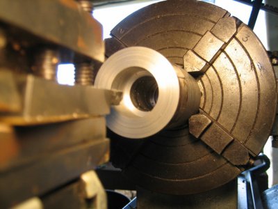
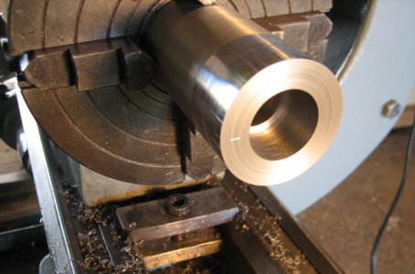
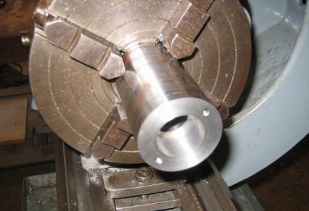
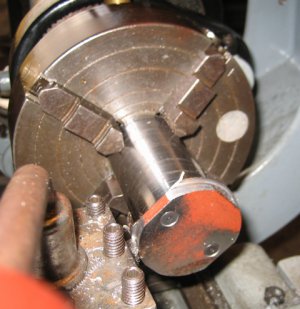
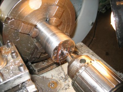
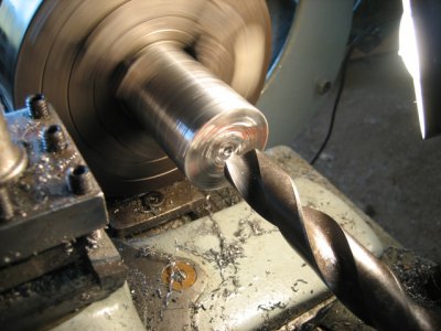
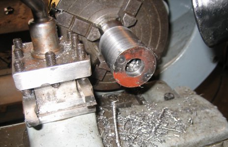
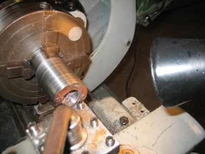
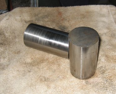
Cut the 12L14 to length, mounted up, drilled through 25/32”, then bore the recess for the needle rollers.
IMG_02.JPG IMG_03.JPG IMG_04.JPG IMG_05.JPG

Cheers Phil
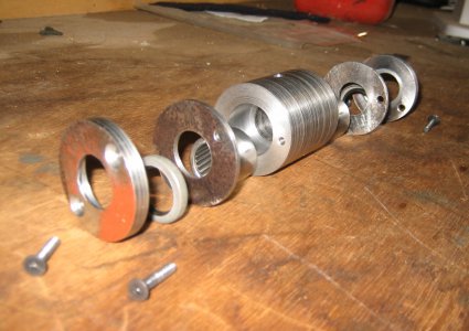
IMG_01.JPG IMG_02.JPG IMG_03.JPG IMG_04.JPG IMG_05.JPG
 
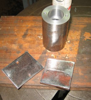
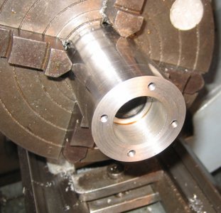
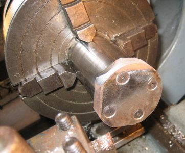
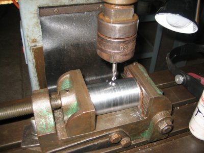
Off to the DP to drill and tap for 4mm + the retainer for the bearing and the thicker end cap to carry the oil seal,
IMG_06.JPG
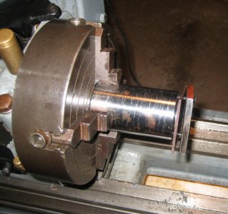
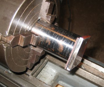
Back to the lathe and fit the end caps, turn to size, centre drill and drill through at 25/32”.
IMG_07.JPG IMG_08.JPG IMG_09.JPG IMG_11.JPG IMG_12.JPG IMG_13.JPG IMG_14.JPG IMG_15.JPG

Cheers Phil
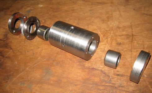
IMG_06.JPG IMG_07.JPG IMG_08.JPG IMG_09.JPG IMG_11.JPG IMG_12.JPG IMG_13.JPG IMG_14.JPG IMG_15.JPG
 
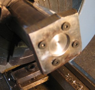
Flip the thicker end cap over, and bore a step to accept the oil seal.
(Because my 4mm holes weren’t perfectly spaced I needed to slightly offset the bearing housing in the 4jaw to make the through hole perfectly centred)
IMG_16.JPG
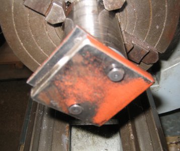
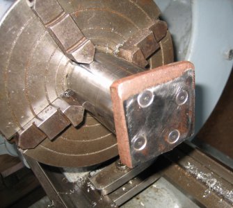
Because one of the housings is blind capped I used a thicker piece of flat bar and bored a recess to take a thrust washer and 4 screws to deal with any extra loads.
IMG_17.JPG IMG_19.JPG
Then flipped it the right way and turned it nice and neat.
IMG_20.JPG IMG_21.JPG
Ball milled a pair of mounting points in each housing and drilled an oil hole.
IMG_22.JPG

Cheers Phil
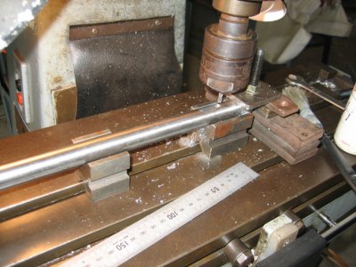
IMG_16.JPG IMG_17.JPG IMG_19.JPG IMG_20.JPG IMG_21.JPG IMG_22.JPG
 
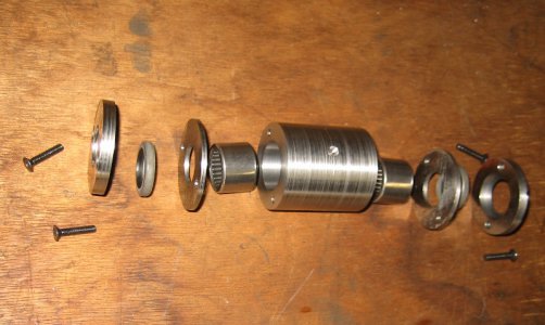
All the bits ready for assembly, used non hardening gasket cement to take up any small flaws in my machining.
IMG_23.JPG IMG_24.JPG IMG_25.JPG IMG_26.JPG
Used a piece of 19mm 4140 for the new shaft.
Milled a keyway for the driven pulley, (there was already a keyway in the pulley but no key).
IMG_27.JPG
Calculated where the step pulley would locate and milled a small flat for the grub screw.
IMG_29.JPG

Cheers Phil
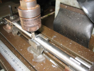
IMG_23.JPG IMG_24.JPG IMG_25.JPG IMG_26.JPG IMG_27.JPG IMG_29.JPG
 
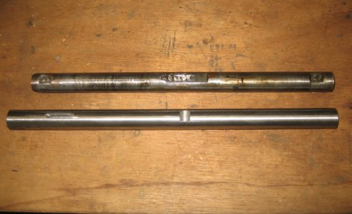
Looks a bit better than the original.
IMG_30.JPG IMG_32.JPG
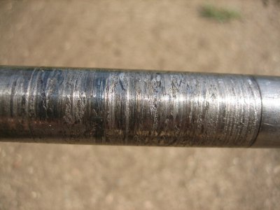
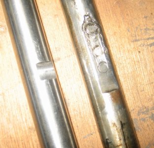
And the damage on the old layshaft.
IMG_33.JPG
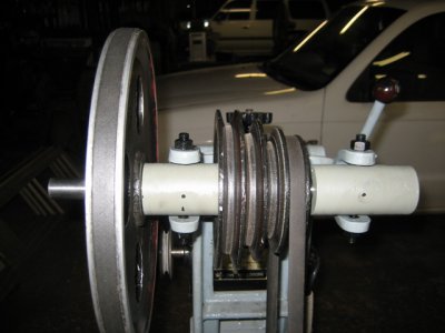
In place ready for action.
IMG_34.JPG

Cheers Phil
IMG_30.JPG IMG_32.JPG IMG_33.JPG IMG_34.JPG
 
Very nice brother. Does that bearing block fit in that housing? If so it sure looks bigger in the pics then it is. Or housing looks smaller.
 
Hmmm? Sorry Chuck, not sure which bit your referring to there?

Cheers Phil
 
In the first pic you made a bearing block. In the last pics you have the whole housing together with spindle, pulley and all. Does that bearing block fit into the cream colored housing?
 
Back
Top