Need To Cut A Couple Of Timing Pulleys

Reddinr

H-M Supporter - Diamond Member
H-M Lifetime Diamond Member
Joined
Jan 5, 2014
Messages
995
So, I have this nice big DC motor with a very low backlash reduction gear on it lying around in the dust. I was thinking about making a bolt-on computer-controlled indexer attachment for my lathe. But, I need to make a big timing belt pulley that bolts onto the back side of the head stock (where the spiders usually are). Probably a 1" wide x 4" diameter aluminum timing pulley. I have a milling machine and a minimum set of lathe tools and end mills. What is a reasonable setup that I can use to make the pulley? I guess I could just buy one and bore out the center to fit the lathe spindle but I'm here to machine stuff... I figure if I could do it for maybe $60-$100 in tooling I would make it, else I would buy it. Thanks ahead of time.
 
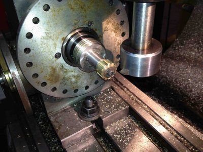
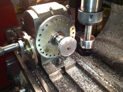
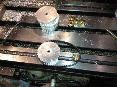
As Bob showed in the video. Specs of the tooth profile for the various timing belts are readily available. An indexing head or rotary table may be more than your budget but will certainly be used often. The cutter is similar to grinding a tool for single point threading acme threads with a flat on the end. The fly cutter I made to hold the tool at 90 deg to the spindle.
These were for the drives on my plasma table.
kXzvAs5thtA-XNoztR0Y6jgZ6v9Ntj7wczydsPC9a9pyQiE0z04Fjc5q-sQkV1Uh8ydw6GGprlXPl8Z0X=w1632-h1224-no.jpg

5eLCjV8RftvVIEecmULoCpldO3c8XFg2AUV9zNbFaHwnJujdLwP3NEoWm6UBsdr2-A-n9gUOj-EryCSin=w1632-h1224-no.jpg

xwZ_BSqOS4K7WwyLoYqE244R4mAthYEFBgO3cJdUDTwwNCCd8UNV0n_LwGUzxrQxDETtFtgUQpze-RFgT=w1632-h1224-no.jpg

Greg
 
Thanks to you both. The video, channel and photos were very helpful. I was hoping to not need to buy an indexer to build an indexer, but, maybe that is what I need to do. The ground tool makes sense, now I know how that is done! I was hoping there was some neat trick for rigging my lathe without too much tooling. I wonder if I could just precisely mark the chuck perimeter and fashion some lock on the spindle. I saw one video where a gear was made by something like broaching. Is that practical I wonder?
 
There are certain numbers of teeth that can be cut with less expensive setups. Do you have an idea of the power to be transmitted and the approximate ratios of sizes of the pulleys? Another option is to use a spindex, which can be had for around $50 and is a useful all around tool. A spindex will give you 360 increments to play with. So you could divide it into 2, 3, 4, 5, 6, 8, 9, 10, 12, 18, 20, 24, 30, 36, 40, 60, 72, and 90 divisions, and probably more that I missed.

Edit: Another quick look and I see I missed 45 and 180 divisions, there still may be more...
 
Last edited:
I'll have a look at a spindex. I'm sure I can make it work with those options. The ratios don't really matter much as it can be 1:1 to maybe 1:4 and still work. It will work as just an indexer so I figured it just needs a stout belt, maybe 1" wide. I can make up the proper angles in the software that runs the indexing motor. I plan to use this to make gears in brass so the chuck will just need to be held stationary while cutting by the stopped motor which will be a tightly controlled servo. Thanks for the spindex idea. I'll have a look at that in the morning.
 
Thanks for the link. That is the way I am going to go. Looks like it will be handy to have around. I have a set of 5C collets so this will do the trick and it fits my budget too!
 
Thanks for the link. That is the way I am going to go. Looks like it will be handy to have around. I have a set of 5C collets so this will do the trick and it fits my budget too!
Do note that doing divisions on a spindex requires counting degrees accurately and then moving that amount accurately. If you write down all the numbers of degrees you need to use, and then double check each one, it will help. Like Stefan said, it is bad to get to the end and only have room left for half a tooth...
 
Back
Top