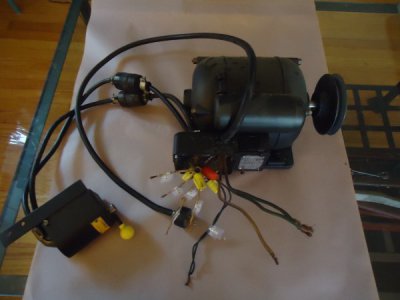
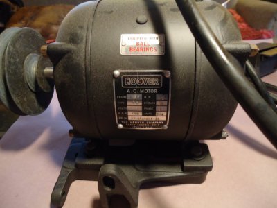
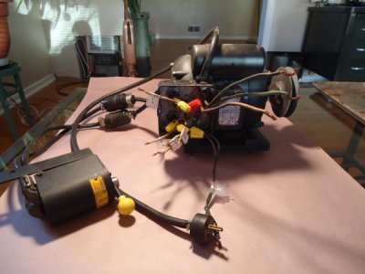
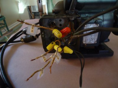
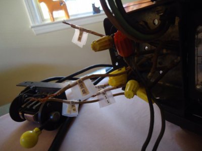
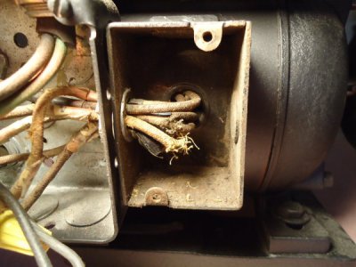
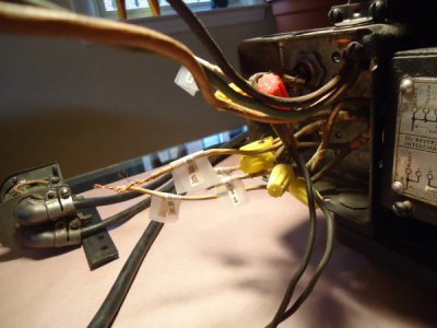
OK. I see the start capacitor housing now. Missed it early this morning. So it is a capacitor start motor, which today is probably the most common type of single phase motor from about 1/4 horsepower to 2 HP. what I would suggest that you do is to remove all of the wire nuts and any other splices and get rid of all of the short pieces of wire. I can see in one or two of the photos some damage to the insulation on a couple of the wires coming out of the motor. Locate an electronics store that sells to hobbyists and small businesses. NOT one with a bunch of computers and computer accessories for sale. Measure the OD of the insulation on the motor wires with the damaged insulation. Tell the counter person that you need a stalk (on most commonly comes in reels of 50 to 250 feet (which you do not need) and 3 foot lengths. One length is all that you need. Tell the counter person what the OD of the good insulation on the motor wires. And you will need one of their cheapest heat guns (which will not most likely be shaped like a pistol).
Pull the wires with the damaged insulation back into the small original box on the motor and straighten it out. Cut the shrink tubing in 1" lengths I think (only as many pieces as there are wires with damaged insulation, so 6 or less). Mash the damaged insulation back down onto the wire. You may find that you need to trim a little of the frayed insulation off but be careful not to cut any wire strands. Slide one piece of shrink tubing over the wire and center it on the damaged spot. Shrink the tubing. Do the next one, etc.
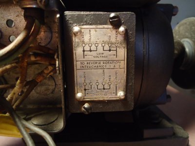
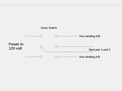
Examine the six wires and see whether or not two are smaller than the other four. If so, those are probably the start circuit. In any case, ID the wires as I wrote this morning. The start circuit, which consists of the start winding, the start capacitor and a centrifugal normally closed switch, The start circuit wires will show a fairly low resistance when you first connect the ohmmeter leads to them. But as the capacitor charges up, this resistance should increase to at least several megohms.
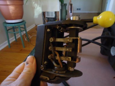
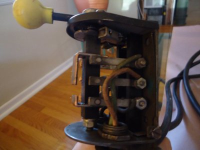
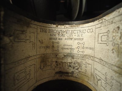
At the electronics place, also buy some extension cord, #12-3 or #14-3 ,aybe 25 feet for the line cord, which after you have ID'd the wires should run to the switch, not to the motor. And a piece of #14-4 long enough to easily reach from the motor to the switch when they are mounted on the lathe. If the switch is not to be mounted to the lathe but to be on the wall or under the bench, you should buy #14-5 instead of #14-4. The green wire should eventually be connected to the motor frame or to the junction box at one end and to the switch frame at the other. You may need to get this at a place like Ace Hardware of Home Depot. Do the wire identification steps and mark the six wires. Once they are ID'd and marked, pull the wires back into the second box and splice them to the #14-4 or #14-5 cordage, taking note as to what color is tied to what. I would use black and white for the two run windings. At the other end, wire the line cord and the motor cord per the switch instructions for single phase capacitor start or split phase motors and for 120, 115 or 110 V. You may need to install one or two jumpers in the switch.
Be careful and don't get electrocuted.
