[Newbie] Need help wiring 220v motor to Asian Lathe

Steve4024

Registered
Registered
Joined
Feb 15, 2017
Messages
6
Hello All;
This is the first time I have ever entered to any type of online forum, so please excuse me if I don't get this right the first try.
I have had this Tida lathe, TD-1236E (12x36) built in 1994 for awhile now.
When I first got it, I didn't have 220v available, so I wired for 110V.
It seemed a little under powered, and would not reverse.
I have since run 220v to it and wired it as the motor plate describes for "High Volt".
Still seems a little under power, but not too bad, I'm used to much larger machines so I can get used to taking light cuts.

My big issue now is trying to figure out how to wire the motor so I can spin in reverse using the lathes lever.
This motor is not original, it is a dual voltage 1.5hp farm motor.
Will it even do what I want?
Does anyone know what the original motor would have been?
I've tried a few different arrangements, trying to figure it out, and when I got a short and popped breaker, I thought I better stop before anything (or myself) get damaged
Nothing did thankfully.
Description of how it is now wired and what I have tried with pictures are on the attached word doc.
(I hope it opens)
Thanks in advance
Steve
 

Attachments

  • Motor conection - Copy.doc
    844.5 KB · Views: 21
First thing is you'll need 5 wires from the switch to the motor. 2 wires will be power and 2 wires will reconnect the red and black to change direction. The 5th wire will be the ground. We'll also need the diagram for the reversing switch.
 
Thanks for the quick reply
Will I need to add wires in the control box?
I don't have a manual, been looking but no luck so far
The switch is a rotary type, it has 4 wires going to the control box, and one jumper wire
When the switch is operated, lever moved up (fwd) and down (rev) the contactor/relay for each operate as they should

I have taken pictures and labeled where the come from and go
I hope it is clear to understand
Steve
 

Attachments

  • Switch conections.doc
    3.9 MB · Views: 15
Steve,

From what I can see, the reversing switch just pulls in either of two contactors (the one on the left, and the one in the middle) for forward and reverse. True?

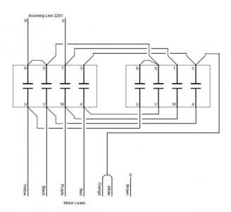
It also appears the motor needs one more wire than the original motor. Many times the motor is reversed by swapping the start winding (red and black in your case) between the two line connections, and this means you need 4 wires plus ground. But your motor, when wired for 220v, swaps the red and black between one line connection and the orange/white wires (tied together). this means you will have to have 5 wires (plus the safety ground wire) between the motor and the controls.

It looks like the right-hand contact (terminals 3 and 4) in the two contactors are not used. I have worked out a control scheme that will work with your motor, but it needs to use these contacts, and they must be normally open (make/continuity when the contactor is energized). If this is the case, then the following wiring will work.

Note that I don't show the intermediate terminals in the bottom of the cabinet, although the wiring will pass through them as before.

Pay careful attention to the wiring between contactors. On top the connections are like-for like (S to S, T to T, etc.) but not the bottom connections!

Hope this makes sense!

StarterWiring.jpg
 
If he changes from 110 to 220 voltage, does he need to change the coils in the contactors ??
 
If he changes from 110 to 220 voltage, does he need to change the coils in the contactors ??
Good catch. Looks like a transformer in the bottom right that will need to be connected for 220v to supply the control voltage. I thought there was only a drum switch and not the contactors.
 
I see a control transformer in there, so presumably the contactors are low voltage. Most likely would have to re-link the transformer primary for the correct voltage.
 
Hi All;
Contactor coils are 24v, transformer input has been switched over to 240v

MrDan, thanks for the schematic
I just checked…..those contactor positions are open, and normally open

On your schematic, the thermo relay(?) is not there (the thing with the white amp dial)
Is it eliminated in your scenario?

When I opened my first attachment with my iPad, the picture was under the text
I don't know if this happened to anyone else, but I think I fixed it and it is attached below

Steve
 

Attachments

  • Motor conection - Copy.doc
    845.5 KB · Views: 10
Steve,

You can (and probably should) still include the overloads in the wiring. It would go as it does now, between the contactors and the motor leads. It should interrupt the yellow, purple, and either red or black wires, pick one (assuming it is 3-pole).
 
Back
Top