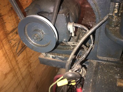
Need advice on TH54 countershaft mounting

aforsman

Active User
Registered
Joined
Sep 13, 2012
Messages
83
I am restoring my grandfather's 10" Atlas TH54 and I'm nearing the point of mounting the motor/countershaft assembly. I got it from my cousin who had it in his workshop in a pile of grease/dust for years without being set up for use. Since I didn't originally remove it from my grandfather's shop, I'm not sure exactly where the countershaft assembly sits in relation to the back leg of the lathe. I bought a piece of 3/4" MDF with the intention of bolting the lathe and countershaft assembly to it and then mounting that to my workbench. I need to know where to drill the holes in the MDF so that everything is lined up and spaced correctly. Since the countershaft is somewhat adjustable, I could probably just install the belt and eyeball it to make it work. I was thinking I could also route slots in the MDF to make the distance more adjustable, but this would be much more work than simply drilling. Otherwise, are there standard dimensions for what I'm doing or does everyone just make it work? I've searched the existing posts and haven't found anything that helps. Any advice would be appreciated.

Allen
 
My 618 countershaft mounting info was in the manual. Should be a file here or on the yahoo group for your lathe I would guess. Also using link belt made getting tension correct pretty easy.
 
Do you have a picture of what you have now? I also have a th54 and if we have the same countershaft setup I can measure things for you.
 
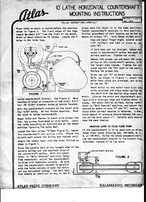
Thanks to all for the info. The pdf file was exactly what I was looking for. I have a link-type belt and a couple of regular V-belts that came with the lathe. All of them measure 37"-38" around the outside. It's obvious the link belt was used between the countershaft and the spindle. I'm guessing one of the others can be used between the motor and the countershaft. Just to be sure, I'll install the link belt and slide the countershaft assembly back until the belt is tight and take a measurement to confirm it falls out close to the 2-1/4" distance shown on the diagram. I took a couple of pics of everything this morning, but I'm having trouble loading them to my computer.

I do have another couple of questions:

From the diagram and from a parts diagram I downloaded from somewhere a while back, it appears that a bolt with double nutting is used between the motor and coutershaft brackets to put tension into the motor belt. I would think that you don't need that much tension in the motor belt since it's running at a lower torque than the countershaft-to-spindle belt. The motor I have is pretty stout. Does anyone use this bolt or simply let the motor "hang" under its own weight?

During a visit with my grandmother a couple of years ago, I was digging through my grandfather's shop and found the manual that came with the lathe. Unfortunately, my grandparents' house was mostly underwater during hurricane Katrina and the manual sat in water for a while. Most of the pages are stuck together, but I'm working on gently prying them apart as I have time. Fortunately, the lathe had already been relocated to my cousin's house, which stayed high and dry. My question is, in addition to this manual, where can I find additional literature, such as the diagram that Wierd Harold provided?

Thanks again to everyone.

Allen
 
...From the diagram and from a parts diagram I downloaded from somewhere a while back, it appears that a bolt with double nutting is used between the motor and coutershaft brackets to put tension into the motor belt. I would think that you don't need that much tension in the motor belt since it's running at a lower torque than the countershaft-to-spindle belt. The motor I have is pretty stout. Does anyone use this bolt or simply let the motor "hang" under its own weight?
...

In an effort to reduce overall vibration, here's what I did on mine:

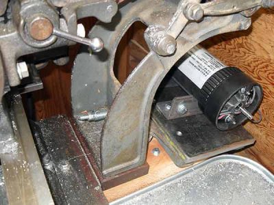
First used an old treadmill motor with a spring around a 1/4" bolt at this location:

2ykzvjk.jpg

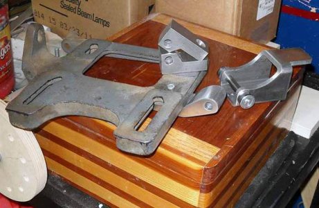
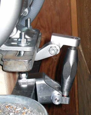
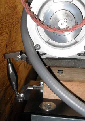
then some time later came up with a way to eliminate the bouncy-bouncy/lock the motor at what I set the tightness to be, then easily adjust for removal. Some parts starting off with:

2s7ff5k.jpg

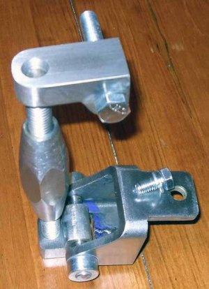
You need to use LH & RH threads, (I used 1/2-13) ended up with:

2w5k3cz.jpg

Just a few turns takes it tight:

30542.jpg

a few turns loosens it enough to pop off the belt:

30545.jpg

30543.jpg

30544.jpg

...sorry for all the pics, didn't mean to hijack... just easier than trying to explain. :)
 
Wow, that's a nice piece of work. No need to apologize - I love the pics. The smaller brackets appears to be machined from aluminum, but the one that bolts to the bench - is that stainless? It appears to be made from a heavy piece of square tubing. I should have it up and running within a couple of weeks. If there's a lot of vibration I may end up doing something similar. Thanks again.
 
That is a nice setup. When I ever get around to restoring my th54 I am going to steal some of that idea, my wife will not be happy when her treadmill suddenly is broken and only good for parts out in the shop.

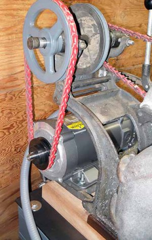
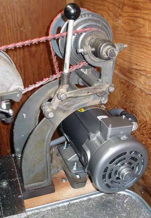
I tried to get some pics of the mounting of mine. Excuse the wiring, I touched it up when I got the lath but only wanted to get it running. Now I can't afford the downtime if I restore it. Pieces at a time in the end.

Ajax-20130821-00719.jpg

Ajax-20130821-00719.jpg
 
The smaller brackets appears to be machined from aluminum, but the one that bolts to the bench - is that stainless? It appears to be made from a heavy piece of square tubing. I should have it up and running within a couple of weeks.

Thanks, all inexpensive steel stock... .25 wall square tubing, 1" square solid stock cut with bandsaw then taken to the belt grinder + a little hand filing. Post pics when you have it running okay... :)

schor said:
When I ever get around to restoring my th54 I am going to steal some of that idea, my wife will not be happy when her treadmill suddenly is broken and only good for parts out in the shop.

Keep a keen eye out on your local Craigslist... I've found 2 so far, free - they just wanted them gone. Motors worked fine, and might help keep the better half happy/ier...

bloomingtonmike said:
Looks like the treadmill motor was replaced with the Baldor.

Yeup. One of the two motors I found didn't have a controller in usable condition, but it was the stronger motor. Did a little homework and went with the KBMD-240D controller as it already was mounted in the enclosure, was easy to add fwd/reverse switch and heat sink. Some time later I ran across this page:

9x20 Lathe Variable Speed DC Spindle Motor
http://www.micro-machine-shop.com/Variable_Speed_DC_Spindle_Motor.htm

and that told me the motor I wanted, a Baldor CDP3440. Couple months searching ebay finally paid off, found a brand new/unused one on Ebay for $175 including shipping. Seller had a "Make offer" button there, so I did... got it for $130 + free shipping. When it arrived I just had to pop in a new $2 - 3/4 hp resistor and was good to go. Really like the setup even though it seems most guys go for VHDs.
 
Back
Top