- Joined
- Nov 26, 2015
- Messages
- 36
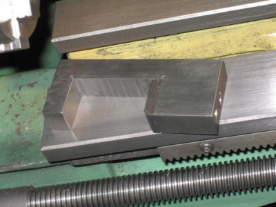
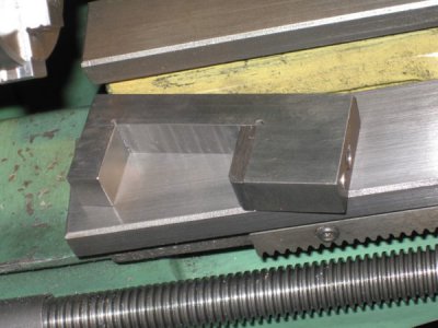
After a very bad crash while the carriage was under power it was time to change the stop that had come with the lathe. The previous owner set it up in such a way that there was a tube welded to a plate which was screwed to the side of the carriage While the carriage was under power I was just a little too late in releasing the lead screw nut lever. The end result was a jam were nothing could be done to loosen the jam. The only way to unjam it was to cut off the stop rod with a dermal tool.
In normal operation the stop was not very convenient as there were three different lengths depending on where the carriage was located for machining. So the original stop was in a sliding tube about 2 inches long with one end at the carriage side and the other against the change gear box. A clasp was used to index the rod and keep it in position. It worked great for hand operation. Under power you had to disengage the lead screw nut and finish the cut by hand.
After the jam I knew I had to change this arrangement.
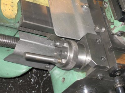
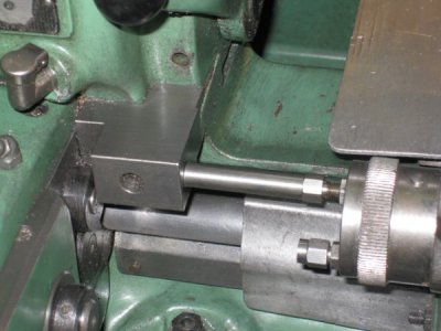
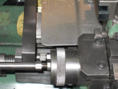
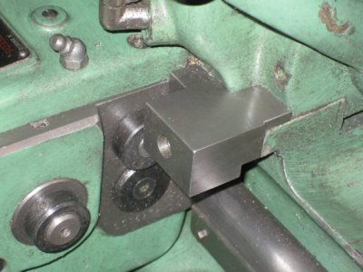
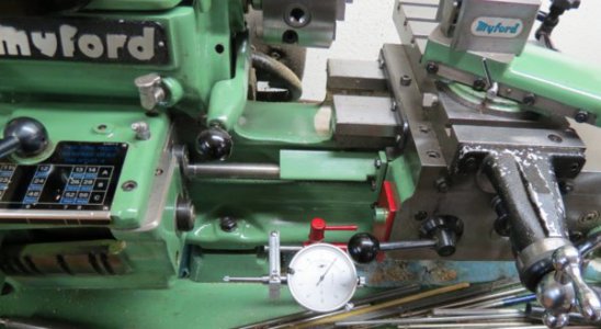
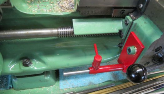
Using the same tube brazed to a longer plate allowed the stop rod to pass under the carriage. Under power if it got to the stop, the worst that could happen was that the rod would just slip in the tube and not jam between the carriage and the gear box.
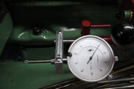
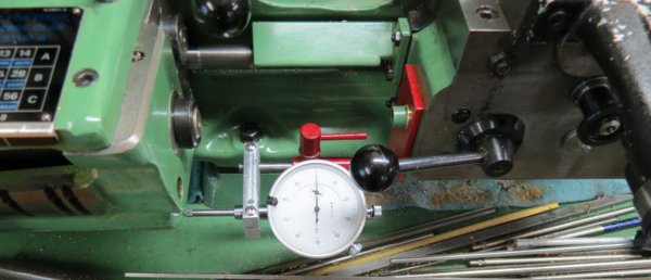
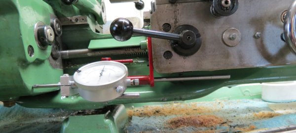
In addition this also allowed for an indicator to be located on the rod. An additional bracket was made in the form of a clamp for the stop rod and the indicator. This located the indicator out of the way of the lead screw nut lever and with an adjustment by moving the stop rod.
The photo shows what it looks like. So far this has been a great modification. I no longer have to change stop rods to get to the right position. And I have the added bonus of and indicator located on the carriage.


