My truly awful week!

hermetic

Active User
Registered
Joined
May 2, 2011
Messages
835
Hi guys and gals, some weeks, the sh*t quite literally hits the fan, and suddenly it is friday afternoon, and you wonder where it all went, and all you want is to go home and forget it ever happened, I call this video, "stress poop and a diatribe" you will learn why when you watch it! Normal service will be reumed next week! I was back in the shop today, and got at least the morning to work on my own stuff! Thanks all for watching, commenting and subscribing!
Phil,
East Yorkshire
UK

 
Hi Phil,

Where to start........

You're right, there is never a good day to be working on septic tanks!

It is good to see you supporting the people that matter in your life; Your mother's freezer and plumbing, your wife's stair lift, your friend's trimmers.
Sure it is work, but you're working for things more important than a pay cheque.

I'm glad you posted the solution you found with all your debug work. The fault is in the relay contacts. Good work!
You have probably saved someone many hours and much money.
You suggested perhaps a short in the power cable to the PCB. Wouldn't it have to be a short in the supply wire from the PCB to the motor?
Perhaps that's what you meant to say.
Of course, it could be a relay with undersized contacts for the motor starting current. The contacts could arc and degrade over time.
I wonder if you could rig in a larger contactor to control the motor.

We could be long-lost brothers.....I was just thinking the other day "Why do I keep volunteering to fix things!".
You stated it clearly: "I really enjoy tinkering. I really enjoy repairing things. Mending things is my reason for existing."
For me it's the learning that comes with it......the pleasure of finding things out.

You mention many of my you-tube favourites.
I also really like YOUR content. It is fair, clear and approachable.
Be assured, that if I did not HATE google so much (an advertising company that pretends to be a tech company!) I would create an account and follow you on you-tube.

I gotta watch more doubleboost......

-brino
 
Good news is that relays like that should not be hard to find and not too expensive. I tend to agree with Brino that the relays are possibly undersized for the starting current. if so then it might just be easy enough to by a half dozen relays and replace them when they weld closed. Sounds like you have a couple of old PCBs so easy to keep one or two ready to swap out.
 
Hi chaps and thanks for all the comments, yes the relays are available, and only £3.50 each, so no problem there! This is to an extent a fault of my own making:oops:, The company I buy the PCB from recomends that the trailing flat 8 core cable is replaced every 5 years, and also should be replaced with the pcb, should the pcb fail. I replaced the pcb only, and I think I paid dearly for my mistake. The cable runs from the moving chair, round a pulley and into the track of the stairlift, it then runs to the bottom of the track, goes round another weighted pulley on wheels, and back to the top of the track where it connects to the power supply. As the chair goes down, the cable is pulled up, and held taught by the weighted pulley, which rolls up the inside of the track. Wneh the failures have occurred, the chair has been at the top, where is spends most of its time. What I suspect has happened, is that there is an intermittent break in one of the power supply cores, the motor has gone into start mode, and with full current flowing through the coil in the motor, the power to the PCB has fluctuated enough to not only collapse the feild in the motor, but also partially drop out the relay, the resultant high back EMF from the collapsing field would arc across the points in the relay, and weld them closed. Once this has happened, and the pcb fuse blows, replacing the fuse will try to start the motor immediatly power is applied, but with the electro brake still on, so the fuse blows again. It may be that a sharp tap on the relay box will free the points, buy I cant get in to the relay without cutting them open as they are sealed to withstand the PCB washdown after soldering. At that price, it is well worth replacing them!
Thanks for your thoughts and interest!
Phil
 
I suppose all the "extra" inductance of the long cables could also have the affect of trying to keep the current flowing as the relay contacts open.

It sounds like you have a good understanding of the entire system.
Imagine what a pain it all is for someone that cannot fix it, let alone understand it!
Costly, too.

-brino
 
You are probably aware but in some cases you can put a reversed biased diode across the contacts that can bleed off the energy when the inductance field collapses.
 
Yes Brino, I agree, and although my training was in electrical engineering, I have done very liitle to do with lifts, so while I may not be an expert on lifts, but I certainly know this one inside out now! Tearing something to pieces when it breaks and fixing it is a good way to learn, especially if there is no other option, and you learn fast!

Boswell, Yes I am aware of the concept, but had not considered it till you brought it up, worth looking in to. given that a new board is about $300. The relays are rated at 20A, but the fuse which supplies the relay bank is a 6.3A sloblo f rating, and it protects the motor not the electronics, they are fused seperately, and that fuse is fine, so no reason to suspect the electronic side of the board is damaged. Board is double sided, but all through mount components, so replacements should not be a problem.
Thanks for the comments, and your interest and advice!
Phil
 
You are probably aware but in some cases you can put a reversed biased diode across the contacts that can bleed off the energy when the inductance field collapses.

I am NOT lecturing, I just want to be sure that anyone referencing this gets the whole picture......for safety.

Diode snubbers CANNOT be used for AC circuits, because they will be forward biased and conduct for half the AC cycle. I don't recall if we were told if this is an AC or DC motor......

A diode is often used across a relay coil that is driven by DC, such that it is reverse biased when the relay is energized. That way it reacts to clamp the reverse voltage generated when the magnetic field around the coil collapses when the relay is turned off. This protects the relay driver (transistor, MOSFET, IC, etc.) from over-voltage.

A diode snubber can also be used across relay contacts for a DC circuit (also shown at the wikipedia link below).

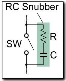
An R-C snubber circuit is often used across the relay contacts for an AC circuit like this: https://en.wikipedia.org/wiki/Snubber
1573258613183.png

-brino
 
Last edited:
Brino, thanks for the extra detail and clarification.
 
Thanks for the info Brino, and point taken! I am getting a bit of flack (on other forums, not here) about posting a new thread every week with a link to my video on the end. ppl are saying I should start one thread, and add to it weekly. I am unsure about this, as it would mean my latest link would be buried at the end of a long thread. I had assumed that the new thread posting every week wuuld quickly expire, and not clutter up the server, whereas a long thread just gets longer, with the vast majority of the posts just skipped over to get to the new one at the end. then again, I suppose it acts as an archive, as nothing (I believe) is ever really expired off the server. What do you guys think? Any advice greatly recieved!!
Phil
 
Back
Top