- Joined
- Aug 3, 2017
- Messages
- 2,437
I have been crapping up EricB's thread with a bit of updates on my #3 (https://www.hobby-machinist.com/threads/the-journey-begins-pm-research-5.83114/) so I figured I'd stop that and put a place for me to post mine! I have been pretty terrible about pictures/videos, but I have a couple that I've attached.
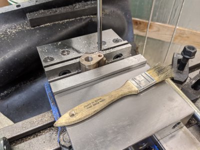
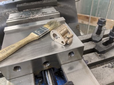
I started with the base. I have a photo of one of my setups, the one where I I milled the bottom. I was quite impressed with this part of the casting!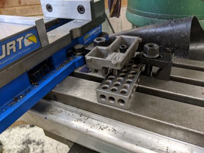
I ended up milling EVERYTHING on the base in 1 go. I DID make a few observations: I milled the cylinder mounting face with the casting 'right side up', but instead of 'spot facing' the driveshaft mounts milled them at the same time so that I would have additional square faces. Additionally, it saved me a setup (having to flip the casting solely to spot-face!).
Unfortunately, I had two problems: First, this was before I was photocopying the plans and was going off of a photo on my phone. I misread the dimension on the oil holes, and drilled them 1/8 instead of 1/16. This ends up being a touch fortuitous as my eagle 66 oiler fits right in the holes
My second problem came when I went to mill the crankshaft holes. They are indexed a distance off the cylinder mounting face, however when I measured that distance out, my hole would have been precariously near the edge of the casting! I ended up going back and re-facing the cylinder mounting face and taking off an additional 75 thou. I had initially milled JUST enough to clean up the casting, which was apparently way too little.
Next, I attacked the crankshaft. This ends up being just a facing operation on two sides of the rod. The dimensions specify this to 3.0" (which the tolerance callout doesn't have a spec for!). I was able to machine it to about 3 thou of that tolerance, just to later find out that it is way too long and I'll likely re-part it down another 3/4" or so.
After that, I started a couple of parts at the same time, since I found my drill chuck wouldn't hold the smaller drill bits and needed to wait for a new one. I had a handful of problems so far due to having tooling that is too 'large' for the project (including a 16" lathe and a nearly-full-size knee mill). I'll still explain my feelings on each part as I went through though:
First, the flywheel. I was able to trivially face each side and drill the center hole on the lathe. The grub-screw mounting was a touch challenging because I didn't have a center long enough, yet small enough to do so. Instead, I just went with a long end-mill and faced it flat, then prayed the drill bit would just find center, and it seemed to work out fine!
However, facing the outside dimension was a disappointing endeavor. I mounted it on the driveshaft with the grub screw and mounted that in my collet chuck. I was able to get it mostly faced (taking REALLY fine cuts, about 4 thou-diameter at a time). Unfortunately, even at 500+ rpm (my max speed), the HSS finishing bit I ground for this (with a slight radius) ended up catching and basically 'threading' the driveshaft with the grub screw as a cutter! It cleaned it up with files and Emory paper, but remaking it (or perhaps trying again after loctiting it to the driveshaft!) might be in order.
Next the eccentric hub: This actually was a pretty easy task. I used my 4 jaw to do the offset, and a custom ground 'parting' type tool to cut everything. I managed to get every dimension on the part sub-thou out of shear luck, save 1. The 'smaller' diameter is actually significantly smaller than the 1/2" dimension. I found that in order to get it to actually be 'round' (meaning 'cut' all the way around), I needed to go about 40 thou smaller in diameter. Since that dimension doesn't particularly matter, and a 0.100" wall on the inner face is sufficient, I decided to go on and live with the smaller size.
The eccentric 'ring' was easy, I popped it into my 6 jaw, then just did some small boring. The set screw on the mill was no issue either.
Next, I did the cross-head caps. These took about 5 minutes each in the mill. I was incredibly impressed with the consistency of the castings! I did a 'back' facing operation on each, then took a bit of meat off of each to hit the dimensioned 'height'. Measuring on the castings is difficult, and the size isn't particularly important, but I'm roughly within the 1/64" tolerance on the height. They are at least consistent with eachother, which I think is what counts. Drilliing was simple with the DRO, and I was impressed that the 1.500" dimension ended up hitting just about dead center of each boss! .750" actually hit dead center of the middle boss as well, these castings/dimensions were right on.
Next, I did the crank casting. I did a simple facing operation on the lathe, followed by drilling/reaming the crankshaft hole. Then I moved to the mill to drill the offset. I was holding it by the rear 'boss' and was afraid that the 4 jaws wouldn't be holding it right otherwise (plus, setting it up that way would cause me to drill into my jaw!). Another grub-screw, and we were done with that!
The connecting rod itself was pretty easy, though the casting had a bit of an 'offset' on it that took a while to file reasonably. I ended up having to go back later and file off even more to make it clear the cross-head cap. Additionally, facing the part that goes into the cross-head cap was a bit of an adventure, since I didn't have it well supported. If I were to go back in time, I would have done a better job at that. Drilling/reaming was easy though!
I did the cross-head-cap entirely in the mill. Annoyingly, it was almost exactly at dimension in width and height already (I'd been hoping to 'file fit' it a bit), but some time on some 1200 grit sandpaper cleaned up the faces and got it sliding perfectly in the base. I cut it within 2 thou on every dimension. However, I was a touch disappointed by the fit of the connecting rod, there is sufficient 'slide' side to side due to the room in the dimension. If I were to do it again, I would have not widened it nearly as much. It is a 1/8" connecting rod in a 5/32" width slot. I'm actually oversized on the connecting rod, and undersized on the cross-head-cap, and still have a decent amount of clearance on both sides.
Last, I did the 'crank bearing', which goes between the crank and the connecting rod. The 5/8" CRS that they gave to work with was too short after cutting the eccentric to hold in my collet chuck or chucks (I tried, it popped out a few times :/) so I used some mystery steel that I had around. I suspect it was 1040, but my dimensions went just right! I filed it almost flush to the connecting rod itself, just enough that the connecting rod can spin, but still making sure it spun freely.
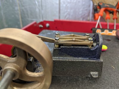
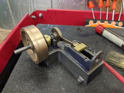
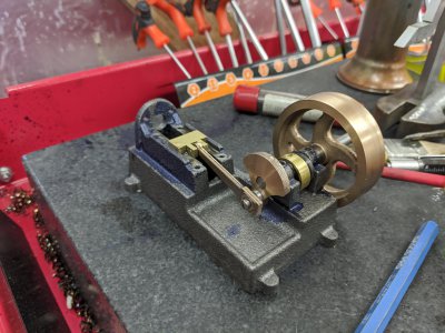
Then, I assembled what I have! I still didn't do the standoffs for the cross-head caps, so those aren't in place and forgot the washer between the connecting rod and the bolt, but was able to 'hand run' what I have so far:
View attachment VID_20200331_170032.mp4
I'm using a pretty heavy oil (Vactra #2) since that is what I have. It moves smoothly, albeit stops quickly (I think because of the oil). I might try some mineral oil when I run it for real. Also, pardon the mess of 'blue' on the base I'll have to clean that before painting.
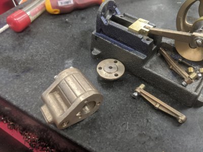
My next step is the standoffs so that I can have it assembled up to that point. After that, I believe I have to start the cylinder casting itself, which I've been putting off. It seems like the most intense and challenging part so I'm not particularly looking forward to it! However, everything else seems to be sized based on that. There's a couple of parts I could probably do (the eccentric rod), but I don't have my die-holders yet
I started with the base. I have a photo of one of my setups, the one where I I milled the bottom. I was quite impressed with this part of the casting!

I ended up milling EVERYTHING on the base in 1 go. I DID make a few observations: I milled the cylinder mounting face with the casting 'right side up', but instead of 'spot facing' the driveshaft mounts milled them at the same time so that I would have additional square faces. Additionally, it saved me a setup (having to flip the casting solely to spot-face!).
Unfortunately, I had two problems: First, this was before I was photocopying the plans and was going off of a photo on my phone. I misread the dimension on the oil holes, and drilled them 1/8 instead of 1/16. This ends up being a touch fortuitous as my eagle 66 oiler fits right in the holes
My second problem came when I went to mill the crankshaft holes. They are indexed a distance off the cylinder mounting face, however when I measured that distance out, my hole would have been precariously near the edge of the casting! I ended up going back and re-facing the cylinder mounting face and taking off an additional 75 thou. I had initially milled JUST enough to clean up the casting, which was apparently way too little.
Next, I attacked the crankshaft. This ends up being just a facing operation on two sides of the rod. The dimensions specify this to 3.0" (which the tolerance callout doesn't have a spec for!). I was able to machine it to about 3 thou of that tolerance, just to later find out that it is way too long and I'll likely re-part it down another 3/4" or so.
After that, I started a couple of parts at the same time, since I found my drill chuck wouldn't hold the smaller drill bits and needed to wait for a new one. I had a handful of problems so far due to having tooling that is too 'large' for the project (including a 16" lathe and a nearly-full-size knee mill). I'll still explain my feelings on each part as I went through though:
First, the flywheel. I was able to trivially face each side and drill the center hole on the lathe. The grub-screw mounting was a touch challenging because I didn't have a center long enough, yet small enough to do so. Instead, I just went with a long end-mill and faced it flat, then prayed the drill bit would just find center, and it seemed to work out fine!
However, facing the outside dimension was a disappointing endeavor. I mounted it on the driveshaft with the grub screw and mounted that in my collet chuck. I was able to get it mostly faced (taking REALLY fine cuts, about 4 thou-diameter at a time). Unfortunately, even at 500+ rpm (my max speed), the HSS finishing bit I ground for this (with a slight radius) ended up catching and basically 'threading' the driveshaft with the grub screw as a cutter! It cleaned it up with files and Emory paper, but remaking it (or perhaps trying again after loctiting it to the driveshaft!) might be in order.
Next the eccentric hub: This actually was a pretty easy task. I used my 4 jaw to do the offset, and a custom ground 'parting' type tool to cut everything. I managed to get every dimension on the part sub-thou out of shear luck, save 1. The 'smaller' diameter is actually significantly smaller than the 1/2" dimension. I found that in order to get it to actually be 'round' (meaning 'cut' all the way around), I needed to go about 40 thou smaller in diameter. Since that dimension doesn't particularly matter, and a 0.100" wall on the inner face is sufficient, I decided to go on and live with the smaller size.
The eccentric 'ring' was easy, I popped it into my 6 jaw, then just did some small boring. The set screw on the mill was no issue either.
Next, I did the cross-head caps. These took about 5 minutes each in the mill. I was incredibly impressed with the consistency of the castings! I did a 'back' facing operation on each, then took a bit of meat off of each to hit the dimensioned 'height'. Measuring on the castings is difficult, and the size isn't particularly important, but I'm roughly within the 1/64" tolerance on the height. They are at least consistent with eachother, which I think is what counts. Drilliing was simple with the DRO, and I was impressed that the 1.500" dimension ended up hitting just about dead center of each boss! .750" actually hit dead center of the middle boss as well, these castings/dimensions were right on.
Next, I did the crank casting. I did a simple facing operation on the lathe, followed by drilling/reaming the crankshaft hole. Then I moved to the mill to drill the offset. I was holding it by the rear 'boss' and was afraid that the 4 jaws wouldn't be holding it right otherwise (plus, setting it up that way would cause me to drill into my jaw!). Another grub-screw, and we were done with that!
The connecting rod itself was pretty easy, though the casting had a bit of an 'offset' on it that took a while to file reasonably. I ended up having to go back later and file off even more to make it clear the cross-head cap. Additionally, facing the part that goes into the cross-head cap was a bit of an adventure, since I didn't have it well supported. If I were to go back in time, I would have done a better job at that. Drilling/reaming was easy though!
I did the cross-head-cap entirely in the mill. Annoyingly, it was almost exactly at dimension in width and height already (I'd been hoping to 'file fit' it a bit), but some time on some 1200 grit sandpaper cleaned up the faces and got it sliding perfectly in the base. I cut it within 2 thou on every dimension. However, I was a touch disappointed by the fit of the connecting rod, there is sufficient 'slide' side to side due to the room in the dimension. If I were to do it again, I would have not widened it nearly as much. It is a 1/8" connecting rod in a 5/32" width slot. I'm actually oversized on the connecting rod, and undersized on the cross-head-cap, and still have a decent amount of clearance on both sides.
Last, I did the 'crank bearing', which goes between the crank and the connecting rod. The 5/8" CRS that they gave to work with was too short after cutting the eccentric to hold in my collet chuck or chucks (I tried, it popped out a few times :/) so I used some mystery steel that I had around. I suspect it was 1040, but my dimensions went just right! I filed it almost flush to the connecting rod itself, just enough that the connecting rod can spin, but still making sure it spun freely.
Then, I assembled what I have! I still didn't do the standoffs for the cross-head caps, so those aren't in place and forgot the washer between the connecting rod and the bolt, but was able to 'hand run' what I have so far:


View attachment VID_20200331_170032.mp4
I'm using a pretty heavy oil (Vactra #2) since that is what I have. It moves smoothly, albeit stops quickly (I think because of the oil). I might try some mineral oil when I run it for real. Also, pardon the mess of 'blue' on the base
My next step is the standoffs so that I can have it assembled up to that point. After that, I believe I have to start the cylinder casting itself, which I've been putting off. It seems like the most intense and challenging part so I'm not particularly looking forward to it! However, everything else seems to be sized based on that. There's a couple of parts I could probably do (the eccentric rod), but I don't have my die-holders yet

