my first jig

dansawyer

Registered
Registered
Joined
Jun 13, 2018
Messages
450
The project is to create a cubic rectangle out of aluminum. Four of the sides are equal, 2 by 12 inches by 1/8. The top and bottom will hold bearings to support a shaft running parallel to the 4 equal sides. I decided to make the parts to all be 'replaceable'. This may sound obvious, however it a first at not holding the the parts in place and drilling and tapping.
The plan is to create a whole design and drill the holes in the correct positions and then assemble. This is a new challenge.
A picture of the simple jig used to drill the pilot holes in the 4 long sides is attached. image_new_3.jpg
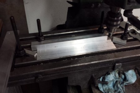
 
Second jig to create the end pieces. The 'vise' holds the end pieces in the correct Y and Z position. The jig limits the X position to the correct position.
 

Attachments

  • jig_2.gif
    jig_2.gif
    150.3 KB · Views: 20
Final outcome:
The objective was to produce a bearing holder for a astroimaging device. The prototype picture is attached. (the bearing holes have not been bored yet)
The objective was met; the parts are interchangeable in any orientation. All the parts were created independently; there was not machining in place. A couple of the holes were near the edge of workable alignment though.
Lessons learned:
My vise is not up the the task. The parts are very good for rough prototyping, but they are not square.
I really need an edge finder.
Using the feeds on the table produce accurate and reproducible results.
Set up takes time and is error prone; but pays for itself.
The next steps are to create the drive gears, the gear train box, and the gear shafts.
I intend to create the gears by turning aluminum disks and turning GT2 timing belts inside out. The gears will be driven by GT2 pulleys.
 

Attachments

  • holder_1.gif
    holder_1.gif
    109.8 KB · Views: 20
Back
Top