My Edm Project.......

brino

Confirmed Tool User
Staff member
H-M Lifetime Diamond Member
Joined
Jan 2, 2014
Messages
9,105
I decided to start a new thread for my home-built EDM project.

I have been thinking about building one for years every time a broke a drill bit or tap inside a work piece. However, cutting hardened metals is just one use, you could also use it for die sinking and "cutting" odd shapes.

This post by Savarin helped to spur me on: http://www.hobby-machinist.com/threads/keyed-washer-spacer.40953/
http://www.hobby-machinist.com/threads/keyed-washer-spacer.40953/
I like the simplicity of his machine. I expressed my intent to build one of my own, and RJSakowski asked that I document my project:
http://www.hobby-machinist.com/threads/keyed-washer-spacer.40953/page-2#post-354709

This will be an on going, long-term project there will NOT be daily updates, especially when I'm back to the office next week :blue:.

I will not go thru much of the theory of operation, see the references below.
Basically an EDM machine uses the spark from an electrical discharge to remove a tiny bit of metal from the work. An electrode is used to deliver the spark to the work piece. The work piece is submerged in a "dielectric" fluid that helps to flush debris out of the spark zone.

Here's a list of the publications I have found during my research phase:

books:
Ramah Machines Metal Disintegrater by Benjamin Fleming
Build an EDM by Robert Langlois
The EDM How-To book by Benjamin Fleming
Build a Pulse EDM Machine by Benjamin Fleming

magazine articles:
A Spark Erosion Machine by C.R. Amsbury - Model Engineer July/August 1976
A Simplified Spark Erosion Machine by Geoff Oakes - MEW #104
A Simple Spark Erosion Machine by Eric Rumbo - MEW #117
Spark Erosion Machine by Peter Rawlinson - MEW #57-60
(MEW = Model Engineers Workshop)

Some good web finds:
A Simple Self-Acting Spark Erosion Machine by Derek Lynas 2008 (http://www.homemodelenginemachinist.com/downloads/files/Easy_Spark_Eroder.pdf)
(Thanks Savarin for mentioning the above reference!)
A spark erosion apparatus (http://mikesworkshop.weebly.com/a-spark-erosion-apparatus.html)

That's it for now, I hope to post some details about my build start later today.
It is already partially running out in the shop.

As always your comments, questions and input is welcomed!

-brino
 
Brino, An excellent start. I shall be following your progress. I have scratched one on my shop to do list as well and your experiences will be welcomed.

Bob
 
The references above cover a huge range of machine variations, some simple, some very complex.
Ben Fleming has three books published and they cover the gambit.
His first book "Metal Disintegrator" uses a welding machine as the power supply, a bolted metal frame, and a vibrating engraver as the mechanical oscillator.
His "How To" book shows a design with a stepper motor controller that senses the voltage at the discharge capacitor to advance/retract the electrode.

my broad categorization of types:
1) simple mechanical vibrator with capacitor charge circuit in series with the electrode control; manual advance
2) simple mechanical vibrator with separate capacitor charge and control circuits; manual advance
3) stepper motor vibrator; automatic advance

Savarin's build based on the Derek Lynas design would be type 1)
The one from the "Metal Disintegrator" book would be type 2)
The designs in the Langlois book and the Fleming "How To" book would be type 3).
Type 3) has a much more complex control mechanism with closed-loop feedback.

Those simple categories do not even consider different discharge voltage amplitudes, polarity, constant vs. pulse voltage, dielectric fluids, pumps, etc.
As with the huge variation of machine types I expect a huge variation in metal removal rates.

I am building type 2).
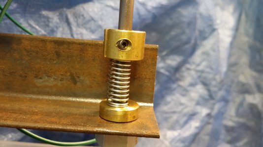
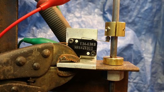
Why? It allows me to separate the mechanical vibrator (spindle mass, head mass, bushings, spring, switch, solenoid) from the spark power supply (source, series resistor, discharge capacitor). It should mean that my components can be chosen/verified somewhat separately.

With type 1) above, if you change the resistor or discharge capacitor values it will also change the current thru the solenoid changing the vibration rate. If you change the solenoid, it will change not only the vibration rate, but also the charging rate.

Since my workshop is in the garage attached to my house I will only be using water as my dielectric fluid. Even though most reference use kerosene for the fluid and state they have had no fires, it _IS_ flammable, and simply not worth the risk to me.

I intend to start with simple copper and brass electrodes. I expect to use hollow tube electrodes most, as they require less time/energy to operate, but may require the operation to be stopped to have the solid metal core broken off and removed.

-brino
 
Already clicked 'watch thread', Its one of those machines i've read some theory on and know some of the application of, but have never actually seen in operation in the flesh. Will be watching with interest.
 
okay, enough research/theory. Let's get onto some build details......

brief description:
I wanted to try some stuff quick and was setting this up on my welding table, so I used MIG to tack many things together.
You'll see there are still a number of pieces clamped together until I get a better feel for where they should be.

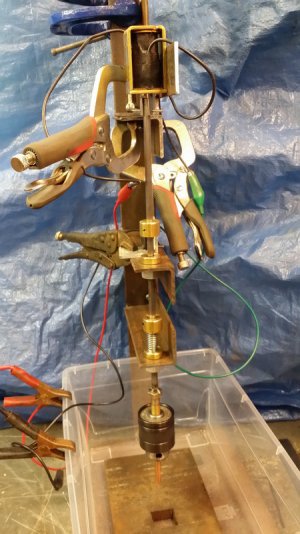
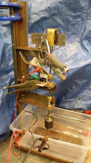
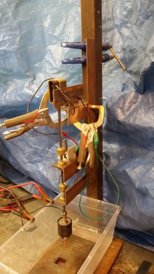
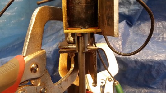
I started with a simple "E" shaped frame. My intent was to have brass bushings in the lower two arms and the solenoid at the top. The bushings I made were drilled and reamed for the 1/4" spindle, and have a 1/2-13 thread for a nut to hold them on the arms. Due to some twist in the simple welded frame the holes in the bottom two arms did NOT line up very accurately. So although I made two brass bushings to guide the vertical spindle I find that if I tighten the one on the middle arm it aligns to the twisted arm and jams the spindle. In all the pictures below the bushing is not tightened onto the middle arm. Two points are enough to form a straight line!

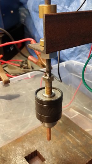
I decided on a 1/4" diameter spindle as I wanted to keep down the total moving mass so I could use a smaller solenoid. Also I used a 3-jaw chuck to hold the electrode as I want to be able to swap out electrodes easily. Since the chuck required a 3/8"-24 thread I found a matching bolt and drilled a 1/4" hole in it's head and tacked it on the bottom of the spindle.

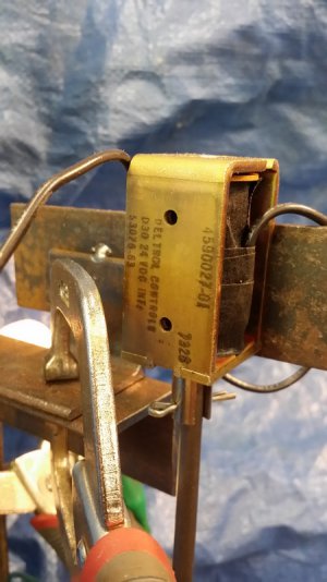
The solenoid I got from my junk bin. It is rated at 24volts, but I am currently only powering it from a 12V battery charger and it's working well.

full_front.jpg full_left.jpg full_right.jpg
head.jpg
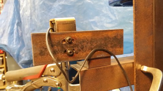
solenoid.jpg solenoid_connect.jpg solenoid_mount.jpg
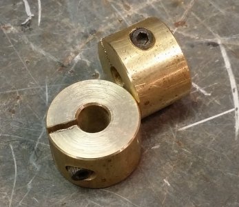
split_clamps.jpg spring.jpg
switch_mount.jpg switch2.jpg

I need to go make a new video, the last one did NOT turn out.....

-brino
 
Last edited:
okay, got the video figured out.
To be clear, so far only the vibrator part is functional. There is no spark voltage source, no discharge capacitor, no electrolyte fluid in the tank and no work piece.

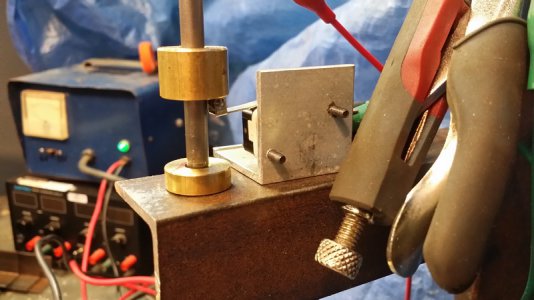
What I have is the vibrating head that falls under gravity closing a switch which energizes the solenoid and lifts the spindle opening the switch, repeat.....
It looks (and sounds!) like the clip below.
It's been running non-stop for the better part of two days.

I can adjust the two split locking collars above the spring and the switch to adjust things.

I notice that I can speed up the cycle time by lifting slightly on the spindle. Moving the spring collar down(compressing the spring more) should accomplish the same thing.

I have a first attempt at a discharge circuit wired up, so I guess I need to get back out to the shop.......stay tuned.

-brino
 

Attachments

  • video2.mp4
    3 MB · Views: 89
Last edited:
I figured out a simple but "good enough" clamp arrangement late last night. Then wired up a spark power supply.
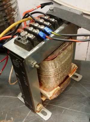
I was trying to find a transformer in the 50-60 VAC output range, but failed. I ended up with one supplying 82VAC out.
It actually has several winding I only use the primary and one secondary.
I have no idea the output current rating of this transformer.
transformer.jpg

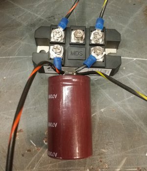
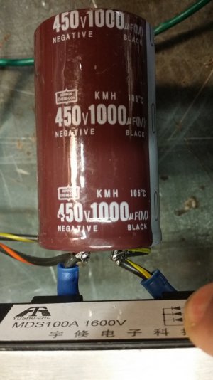
I fed that thru a full wave rectifier (using only two phases of a 3-phase part; rated 100A 1600V) to a 1000uF, 450V capacitor.
bridge1.jpg bridge_and_cap.jpg

At that capacitor I measure 114VDC
Please be aware that this kind of voltage could be harmful.

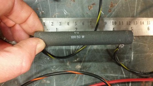
The negative lead runs thru a 10-ohm, 50Watt series resistor:
series_resistor.jpg

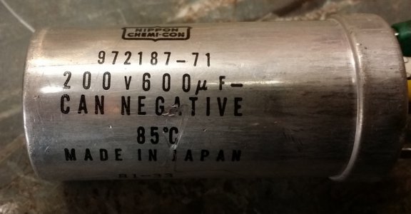
Then to the "spark capacitor":
spark_cap.jpg
This capacitor is directly in parallel with the workpiece/electrode.
I had the work piece connected to positive and the electrode connected to negative.

This afternoon I finally had a chance to power it up!
The first real tests were on a cut off of 1x2 steel bar that was laying around.

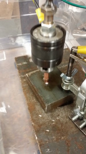
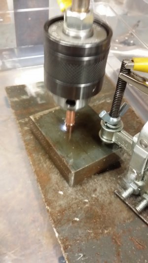
Here's a couple still shots of the sparks in action:
block1.jpg block2.jpg

and some video is attached below.

The resistor does get warm in use.

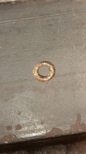
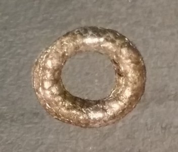
Here's the damage to the block after just a couple minutes of run time:
crater1.jpg crater_in_block.jpg

Initially I thought the electrode had welded to the block at the end because I could not slide the block out, but no! The hollow electrode was actually sitting in the groove and not allowing me to slide it.

More to come!
-brino
 

Attachments

  • 20151229_155127.mp4
    23.9 MB · Views: 69
  • 20151229_155204.mp4
    10.6 MB · Views: 56
Very Cool! :encourage: I guess I'm going to have to build one!:)
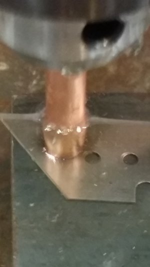
 
Well that was too much fun to stop......

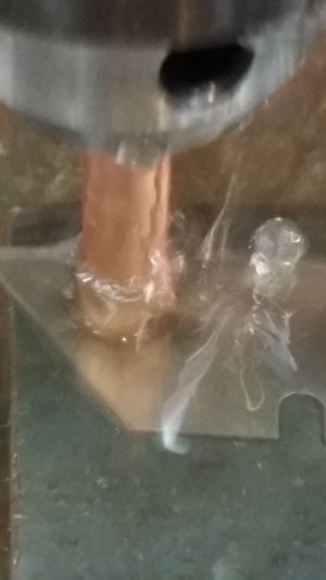
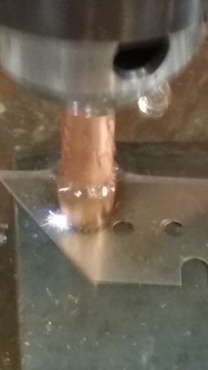
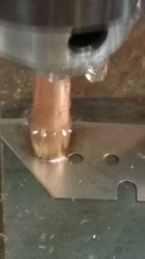
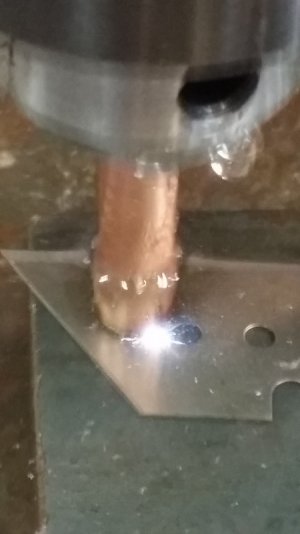
Next up was a couple of utility knife blades.
some still images:

blade1.jpg blade2.jpg blade3.jpg blade4.jpg blade5.jpg
some videos are attached below.

You can tell it's working well when small plumes of black debris come out of the spark area.

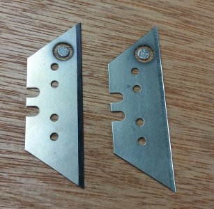
Here's the results; top side:
blade_holes1.jpg
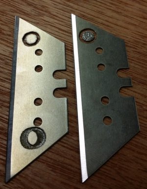
back-side:
blade_holes2.jpg
they only took 10-15 minutes each.

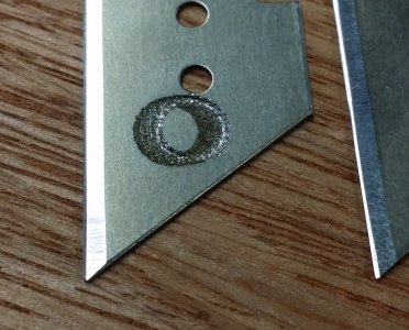
You see at one end above where I started it and things shifted creating a "smear" it looked kinda neat:
blade_smear.jpg

I built this unit with just a simple fixed stand with no easy method of advancing the electrode.
I was going to wait until I had "proof of concept" that this would actually work.
At this point I see that as a requirement, I had to get my son out to adjust the blue clamps at the top to lower the electrode.

Well, that's all for today.....what a fun day!

-brino
 

Attachments

  • 20151229_162233.mp4
    10.7 MB · Views: 50
  • 20151229_162322.mp4
    16.4 MB · Views: 43
That's pretty cool. If you haven't already, I think you need to occasionally throw your head back and let out a blood curdling Bwaahhh- ha-ha-ha just like the aspiring mad scientist that you are. :grin: Mike
 
Back
Top