Monarch 1944 12" CK

rabler

Addlepated tinkerer
H-M Lifetime Diamond Member
Joined
Feb 25, 2021
Messages
3,271
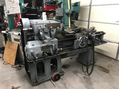
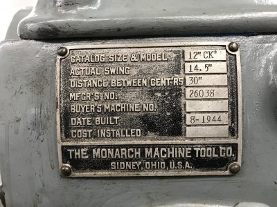
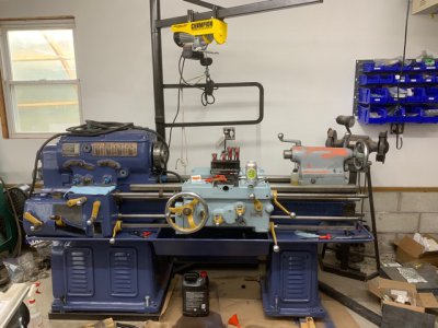
I'm going to try to start a running history on my project lathes. First project lathe I bought is a 1944 Monarch 12" CK. It's actual dimensions are 14x30, Monarch has a history of understating the swing. I found a Craigslist ad for this machine about 2 years ago, in a town 20 miles away. It ran, included a Shars quick change tool post with two or three insert holders, drill chuck, 3 and 4 jaw chuck, taper attachment, steady rest. The whole machine weighs somewhere around 3500 lbs. Cost me (as I recall) $2200. Hauled it home on my gooseneck.

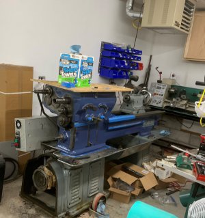
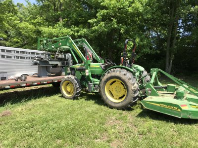
Challenge was that my tractor lift has a capacity of about 3200lbs. I had to partially disassemble it on the trailer to lift it into the shop. Picture below with the 8' mower deck on the tractor as a counterweight. Second picture is re-assembled in the shop on a set of pallet jack wheels (design idea from Tom Lipton/OxTools).

IMG_2665.JPG
IMG_2670.jpgIMG_2691.jpg

Edited to add: Note these pictures date from May and June of 2019.
 
Last edited:
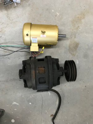
Second step was to deal with electrical. Monarch offered this model with a 3HP or 5HP 3-phase motor. Not having any other 3 phase equipment, I wanted to run this on a VFD, and decided to replace the old motor as it's bearings were shot. I could have replaced the bearings, but I'd read enough about VFD's to feel more comfortable with an inverter rated motor.

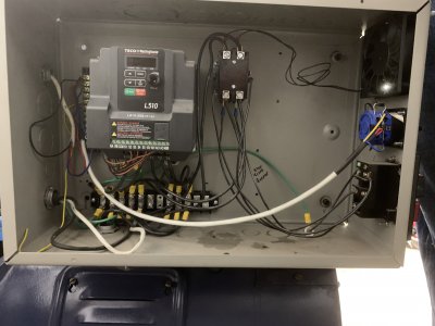
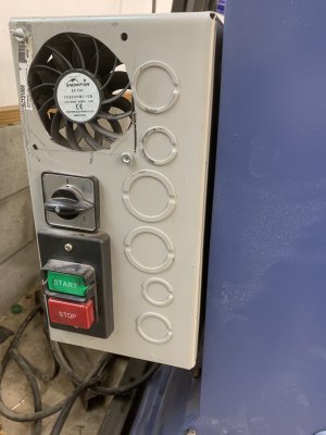
I had to fab some spacers as the new motor was a smaller frame. The original motor was a 1200rpm, and this CK had a top spindle speed of 550rpm. I did enough research to find that Monarch offered these in something like and 800rpm spindle speed just by shipping a 1800rpm motor, and of course a different speed-gearing placard, so I went with an 1800 RPM motor as my replacement. The VFD is a Techo L510 model, single phase 220V input. I put a contactor in front of the VFD, a fan in the box, and originally wired it up to a 4 position switch for the VFD speed input, position 1 for future use with a speed potientometer, 2 for 40Hz giving the same speeds as the 1200rpm motor, 3 for 60Hz giving the rated speed of the motor bumping the top spindle RPM to around 800, and 4 for 80Hz giving 2400rpm or about 1100rpm top spindle speed. Wiring the 4-way switch that way into two inputs on/off inputs on the VFD requires a diode. The contactor goes on the line side of the VFD (never on the motor side!) associated with the red/green on-off buttons. I didn't worry about wiring it in a magnetic switch configuration since the VFD is set to not resume after power loss.

The Monarch factory run/stop push bottons were an interesting arangement. These buttons are on the front lower right of the quick change gear box. The buttons push on long rods that go to rocker arms in the back of the machine, which is where the original on/off switch to the original contactor lived. I replaced this switch with a couple of low voltage momentary contact pushbuttons set up to the VFDs run/stop input. Note that this model Monarch does not have reverse. The spindle only turns the normal "forward" direction. There is a feed reverse lever on the apron that allows feeding left or right (or in/out) or allows for right/left threading. The feed reverse mechanism has stops so the carriage can be set to stop feeding at a specific point for feeding/threading. I thought about adding reverse (just basically enabling it in the VFD) but the internal design of the headstock has some gear dogs that are rounded on one side to slip in easier. That means the dogs won't hold well if the spindle is running in reverse. At least that is what I read, and opted to not enable reverse.


My fan cutout looks horrible. Should have used a big hole saw instead of trying to use a jigsaw. I'll cover it with a screen one day.

This gave me a running machine even though I knew more work was needed. Much more encouraging for me to so little steps and come back to a running machine than to have a shop full of parts leading up to one big rebuild.

IMG_2687.jpgIMG_3323.JPGIMG_3324.JPG
 
Last edited:
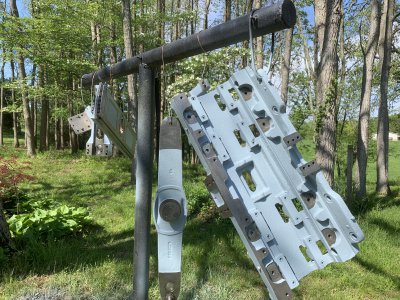
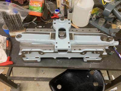
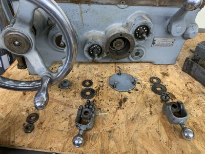
After getting the motor and VFD done, it was fun to just push a button and watch it spin. I certainly like taking things in increments that I can see some results. I decided the next step was to clean and rebuild the taper attachment. Keith Rucker had a pretty good video on youtube on rebuiding a Monarch K, and with a very similar taper attachment. I decided that looked like something I could tackle. Mine was a completely frozen up. Took it completely apart and repainted the castings.

I picked up a bunch of new bearings from the local bearing supplyhouse. Total of 16 small roller bearings. I also got new brass shim washers (.004) for those bearings from McMaster. Those bearings are all held by offset (camming) studs, so on reassembly they can all be adjusted to run without gap on the taper slide.
IMG_3006.JPG

I picked out this paint color online right at the begining of the pandemic. Sherman Williams was doing curb-service only. I was shooting for something a little more grey but it came out more blue than I really liked. I actually sprayed these, but have since gone to prettymuch brush painting everything.
IMG_3007.jpg

Edited to add: Note these pictures came from May and June of 2020.
 
Last edited:
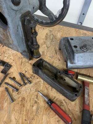
Next step was to take the apron and carriage off. Monarchs use an oil pump in the apron that is activated by turning moving the carriage position crank, either manually or by power feed. That pump uses a felt filter, and a distribution system through a bunch of copper oil lines. Both the filter and the oil lines are prone to getting plugged up, especially if the system is run dry. Since that lubricates all of the bearings in the apron as well as the carriage over the bed, and the cross-slide over the ways it is critical that this system be cleaned out. This was my first "complex" disassembly, where it wasn't clear even looking at the exploded parts diagrams, exactly how things came apart. I used my cell phone and took pictures of EVERY steps. Literally hundreds of them. The really critical pictures were ones where I lined up all the parts on a given shaft to show the order of the bearings, washers, bushings, gears, etc

First picture is the oil pump in the side of the apron
IMG_3042.JPG
IMG_3044.JPG
The other useful pictures where ones from literally as many angles as I could get of what everythign looked like before disassembly. I have seen a suggestion of using a video camera while doing this and that sounds useful, but I wouldn't want to count on it.
IMG_3031.JPGIMG_3038.JPG

Figuring out how to best clean things was a major challenge. Ultimately the biggest tool in this seems to be elbow grease. I tried brake cleaner (nasty) "goop" hand cleaner (OK but nothing magic). I have an ultrasonic cleaner and tried that for smaller parts, they're not very effective for anything other than a fine film. I got a large parts washer, which is useful if you can heat it. I bought a livestock bucket heater (jeffers.com), that will heat my parts washer up to above body temp. These old machines with heavy gunk can load up a parts washer pretty quick, and mine sits in an unheated shed. Best thing I've found is to use the bucket heater in a 5 gallon pail, let the water get as hot as the heater will go (maybe 110), and use chemical gloves, gel dishwasher soap, a scrub brush, and rags, lots of rinse and repeat. Many folks recommend acetone or mineral spirits as a final wipe before painting. Rustoleum spray cans have in the past few years gone from recommending mineral spirits to soap and water. I've found 99% isopropyl alcohol works quite well, cuts oil easily and drys quickly and I since that's just rubbing alcohol I'm less worried about toxicity, my understanding is acetone is not something you want to get large skin exposure due to organ toxicity(?).

Edited to add: Note these pictures came from late June, 2020.
 
Last edited:
After getting the apron fully disassembled, cleaned, painted and reassembled, I proceeded to do the same with the rest of the carriage. For the carriage I carefully cleaned out all of the oil passageways which lubricate the ways as well as the cross slide. Those don't provide lubrication to the compound's ways or to the the compound base where it rotates, so I drilled 1/8" holes for those and installed ball oiler caps to provide lubrication to those areas. I replaced the thrust bearings on the cross slide leadscrew. Unfortunately those size thrust bearings are not available, so I made up some small bushings to adapt a close fitting bushing. No good pictures here unfortunately, as none of those mechanisms where complex enough to need a photo guide for re-assembly.

When I put the carriage and apron back together and ran the lathe, it was pretty clear that the quick change gear box was making some obnoxious noises So that was next on the clean and disassemble list. I'd already taken the cover and face plate off once as part of removing the apron, getting the lead screw reverse rod out is a complex process.

One thing to say in all of this is that Monarch loves to put things together with taper pins. These are industry standard (you can get them through McMaster). Taper means 1/4" per foot. That taper is hard to detect across a 2" pin when it is driven through a bushing, and a little mushrooming from previously being hammered in/out can total obscure which is the larger end. Several place Monarch uses both a set screw and taper pins. This appears to be in places where the set screw was probably used to get the alignment correct before hand drilling the taper pin holes. Since the taper pin holes are hand drilled, they are NOT interchangeable. So the spindle speed levers (which need to come out to get the QCGB off) have both setscrews and taper pins, and these levers are not interchangeable even though they look identical otherwise. It's possible to rearrange things until you get a fit, but a few discrete marks with a carbide scriber are helpful. Also, Monarch is fond of using a locking set screw on top of a set screw. When digging through greasy parts these things can be easy to miss and more than once I was baffled why something wouldn't come apart until realizing this.
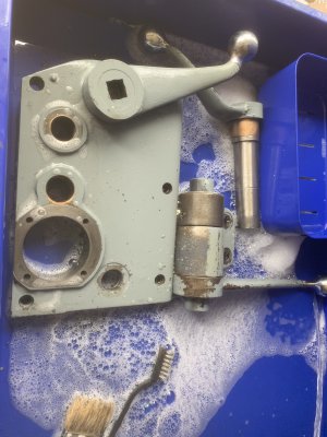
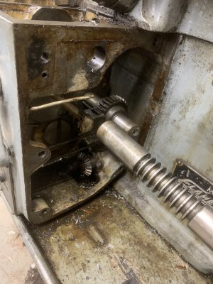
IMG_3019.JPGIMG_3020.JPG

The quick change gear box was a real challenge is dissassemble. I relied heavily on posts on some other forums, and several youtube series, Keith Rucker & Machining360 in particular have some good series on older Monarchs. They are fairly similar in design across the different models in the 40's and 50's, so it isn't critical to find an exact match. The CKs, CKKs, CYs, CW's, K's, and early series 60's even use many of the same parts diagrams, at least the diagrams I received from Monarch.

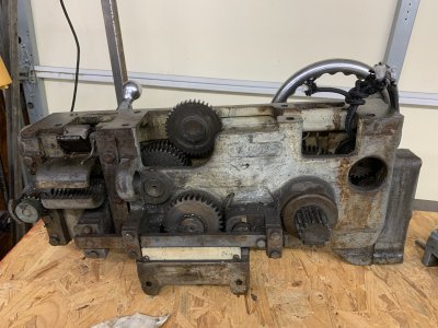
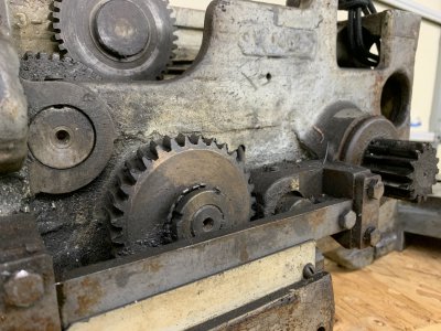
I'm certainly glad I went through that gearbox, it was a mess and many of the bearings were in bad shape, as well as several bronze bushings. Here's what the backside of the gearbox looks like after coming off the lathe:
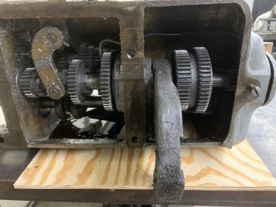
IMG_3124.JPG


Lots to be learned about how these lathes work while doing all this. For one thing, while they look from the outside like they are fairly closed up, both the apron and the gearbox are not sealed and have fairly large areas where chips can get into the works (especially with the help of an air gun). For the gear box, the only oil comes from the two cups on top of the gearbox, which really do need to be filled with a shot of oil every day the lathe is going to be used. Also, the tumbler (handle on front of the gearbox under the feed/threading selection chart) needs to be in the leftmost position when oil is put into those cups, or it will not get oiled.

The quick change gear box was quite challenging to get apart, and contains a lot of bearings. Between the taper attachment, apron, gearbox, and end gears I probably have $1000 in bearings, as well as a lot of shop-made bronze bushings. I probably could have gotten away with not replacing some of the bearings but as complicated as these things are to disassemble and reassemble it was not something I wanted to redo.
 
Looks like you are doing a bang up job.
Please continue to share your progress.
 
After getting the gearbox rebuilt, it was time to make the lathe look somewhat nicer. I spent quite a bit of time cleaning and painting. While I started out using a compressor and paint gun, I soon decided that a brush was going to give me a finish that was good enough for my standards. In part that was due to size, things I could disassemble were easy enough to take outside for spraying, but a small densely packed shop was not conducive to spraying.

I used Sherwin Williams industrial alkyd enamel, which is only available here through one of their commercial/industrial stores. Many of the earlier smaller parts I stripped completely using various paint strippers. The later parts I settled for cleaning extensively and then using a wire wheel on anything that looked like loose or flaky paint or exposed casting. After the wire wheel treatment I hit anything glossy with 120 grit sandpaper, just hand sanding lightly, to scuff the surface for a good bond.

After the first coat of paint, I put a little glazing putty in any areas that looked severely mottled, like where the original paint had been chipped, and sanded that smooth.

Industrial enamel dries slowly, especially the darker colors. I found that two days in cooler weather (shop heated to 60 plus an infrared lamp) is needed to dry to the point of being handleable. And really several weeks before you want to expose it to solvents or oil (including cutting oil or water soluble coolant oil).

In this process I cleaned the flushed the headstock. The first challenge was getting the cover off as it had been sealed down with RTV. I used a bunch of utility knife blades, driven under the cover, as wedges to get it loose. I’m really hoping to avoid having to disassemble the headstock. In many ways it shouldn’t be more complicated than the qcgb, just a bigger scale. It did need a good flush inside. ‘Unfortunately it is difficult to clean in there as it is fairly compact. Later, In working on my 10EE, I discovered a very useful approach. A 1 gallon garden sprayer filled with diesel fuel can be pumped up and used to flush things. Basically a super-sized version of spraying everything with wd-40. First thought might be that the diesel would soon ruin these cheap sprayers but I’ve left one partially full of diesel for months and still works.
 
Last edited:
To paint the bottom casting and chip pan, I got my gantry over the thing and lifted the headstock and bed off the support casting that holds the motor. While it was off I also put some gaskets around the bolts that hold that together through the chip pan, as that was leaking oil.

Hosting the lathe, after manhandling the headstock casting off, and using the crane to hoist the carriage and apron off and on got me thinking about adding a backsplash, jib crane, etc. I decide that setting the lathe on top of a frame of steel 2x2 square tube, with that frame extending a bit out the back of the lathe, would make a good base for the jib crane, and give a place to secure a backsplash. So I built that up. I got carried away and actually used taper bearings in the pivot for the jib mast. The vertical is 3" round x 3/16" DOM tube, with another piece of 2x2 square tube as the horizontal. The center through the pivot is 1.25" OD x .75" ID 4130 tube, threaded top and bottom so it comes apart. While the electric hoist is rated at 440 lbs, I wouldn't want to put more than about 200lbs load on this, that was just the smallest hoist I found. The hoist is on rollers to it can run in/out on the jib.
IMG_3273.jpg
You can see in this picture that it's getting close to being back together. The apron rod support on the tailstock end is missing. Tailstock needs work. Etc.

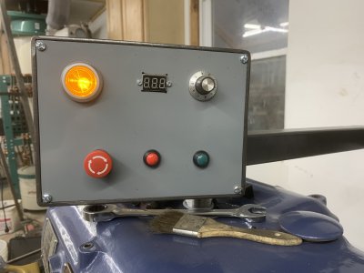
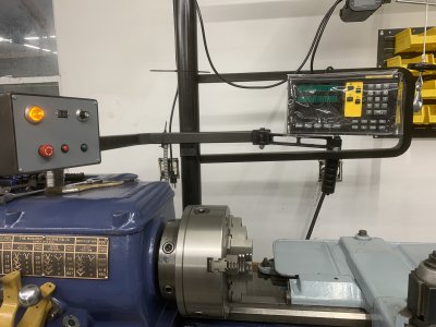
When I powered it up after this to test it, and made a few cuts, I decided I to add a few things. Once was a control panel above the headstock wired back to the VFD. The other was a good DRO (DRO Pros). Test running also decided I needed to do a little work on the clutch (replace some small springs basically), and replace the bearings under the end-gear banjo. After replacing those bearings I still didn't like the noises from that end. A little experimenting with touching the gear hubs while it was running led me to realize I hadn't properly set the backlash on the end-gear banjo after re-assembling the headstock, it was too tight and the gears were rattling. The bearings had definitely needed replacing, but getting the backlash set right made for a really nice smooth running lathe.
IMG_3327.JPG

The top left yellow light just indicates the power is on through the main contactor to the VFD. The buttons along the bottom are e-stop, stop, and run. E-stop and stop are both NO switches wired in parrallel to the VFD, I just prefer not to have to turn the e-stop reset after pushing stop. The LCD in the middle is a cheap voltmeter I got off Amazon, measures DC volts from ~3v to 24V in 1/10 volt increments. It is powered by the voltage it is measuring, so the display dims out and dies just under 3V. I wired this to the VFD analog output and programmed that output for percent max power. The way it is configured, 7.5 on the display means rated HP (3HP) load on the motor, 10 would be 4HP. 10.0V is the max output on the VFD analog scale. Not critical but it gives me an idea of how much load I'm putting on the motor and VFD.

The dial is a potentiometer connected to the VFDs speed input. To use that potentiometer, I have to set the dial on the back control box to the #1 setting. Instead I have been leaving it set to 3 for 60Hz, and shifting gears. I'm not pushing the VFD/motor combination for a large speed range, 40 - 80 Hz, whether I use the rotary knob in back or the potentiometer.

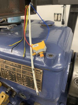
At some point I'd like to add a hall effect RPM sensor, will just have to cut another hole in this panel.
IMG_3334.JPG
IMG_3335.JPG
 
Back
Top