- Joined
- Sep 22, 2010
- Messages
- 7,222
Monarch 10EE Toolroom Lathe - Page 1
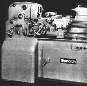
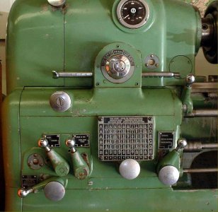
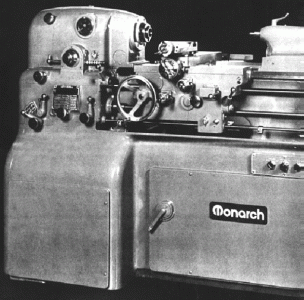
Introduced in 1939 with a 12 inch swing (not the 10 inches that its name would suggest) and a capacity of 20 inches between centres, today the Monarch 10EE Precision Toolroom lathe has a well-established reputation as one of the finest small lathes it is possible to buy. The first two examples produced,, with serial numbers EE-6156 and EE-6207/8, were shipped, respectively, to the Precision Scientific Company Chicago, IL and the Woodward Governor Company of Rockford, IL. The lathe followed and improved upon an already-established design path intended to produce the most accurate of work and the finest of surface finishes: the bed was mounted on a massive and heavy one-piece cast-iron stand with the entire drive system isolated inside and the headstock spindle turned by belt. The arrangement provided great stability and removed any chance of vibration from motors or gearboxes being transmitted to the workpiece. In addition, whenever sliding and surfacing feeds were selected (as distinct from gear-driven screwcutting) the precaution was taken of using a flat-belt to drive the gearbox - so isolating the drive from uneven gear impulses that might spoil the surface finish. Early machines, made until a change-over that lasted through 1944 and into 1945, are now referred to as the "old height" models and may be distinguished from later versions by the (beautifully-made) circular feeds-and-threading selector arrangement on the face of the gearbox. There were two types of "round" box: one used a rectangular knob that was pushed in and turned to select a gear range and another version where the ball lever was first rotated to disengage the gearbox, the centre wheel turned to select the range and then the ball lever turned again to re-engage the drive. One sub-version, the very rare ELSR, had a form of electronic leadscrew reverse incorporated, a fitting intended to speed up and make safe repetitive screwcutting operations. The screwcutting gearbox box was able to generate 30 different feeds from 0.001" to 0.0075" per revolution of the spindle and 50 combinations of threads from 3 to 92 t.p.i; a further distinguishing feature of these very early models was the open changewheel drive to the screwcutting gearbox - later lathes have the gears fully enclosed in an oil bath case. Although found very infrequently, it was possible to order a dual inch/metric screwcutting gearbox - an example is shown lower down this page.
As the lathe was very expensive it is likely that some customers would have ordered some changes to the specification, or had extra features included. One such, found on a 1942 example, was an unusual electrical reverse to the leadscrew. This mechanism was driven by a motor and gearbox, mounted above the ordinary screwcutting gearbox, together with a control rod that ran through the carriage to the tailstock end of the bed. Attached to the rod were collars that could be locked at any position--when the carriage struck a collar. the rod was pushed into the box and the drive reversed.
As early 10EEs were built during WW2, a shortage of materials and components caused their specification to vary slightly from month to month. While some, close together in serial number, had V-belt drive others had flat (though this may have been a customer preference); a number of different of DC control boxes were employed and variations around the complex drive system persisted for several years with the types coexisting side by side until a full change-over was completed. On the earliest machines the spindle was driven by a V or flat belt from a massive hydraulic/hydrostatic variable-speed unit of Sundstand manufacture that provided a speed range of 25 to 2500 rpm. In 1941 this was replaced by a three-phase motor driving a 3 h.p. DC generator that provided power for an electronic variable-speed drive system* - a not dissimilar arrangement also being used on the EnglishCromwell toolroom lathe. However, some experimentation appears to have been conducted by the factory (or a shortage of components encountered) as subsequent changes involved three versions of the Reliance VS Motor Generator unit, then a "WiaD" drive, a Module Drive and finally the Monarch DC type. Some details: in 1949, in line with new developments in electronics, the Reliance rotating motor-generator set (DC) arrangement was replaced by a system (WiaD) that used electronic-tube controlled thyratrons to rectify AC current to a variable DC voltage to drive a DC motor (multiple vacuum tubes being used to control the rectifier tubes). This set-up became better known as the "works in a drawer".In 1950/51 the drive was again redesigned and improved and then, in 1960, the WiaD superseded by fitting a more powerful 5 h.p. motor and a "module drive" that used an all-solid-state electronic module to control the electronic components (with the exception of the thyratrons); around 3,000 lathes were supplied with this system. In 1984 further alterations were made with an entirely solid-state DC armature regenerative drive replacing the now old-fashioned thyratron tubes and finally, in 1995, a change to one of the increasingly popular and less-expensive AC-inverter types that were finally ousting the DC models. By now the lathe was equipped as standard with a 7.5 HP AC TEFC motor - and this unit was also made available for field retrofits and factory rebuilding. Today, when a machine is factory refurbished, it will be fitted with either a 5 h.p. or 10 h.p. 3-phase motor - both having their speed varied by a modern inverter (VFD). For home-shop use the most convenient and reliable drives are the early Sundstrand, WiaD and Module types. A single-phase motor can be used to power the Sundstrand while both the WiaD and Module drives would have been be fitted with single-phase motors as standard when new. Only the coolant pump on the latter two types is 3-phase - and this can be run from a simple and inexpensive static converter. The motor generator units need to be powered from a proper rotary-phase converter (a static unit will be unhappy) while the Monarch Electronic DC drive will only run on a true 3-phase supply (either from the mains or a "phase-perfect" electronic phase converter). The drive motor (integral to the motor generator) is about 6.5 h.p. - a figure to use when working out the RPC size required. One unit recently tested with the MG unit was fitted with a 15 h.p. RPC and was pulling 20 amps at 240 volts out of the wall - and that was without the spindle running. It was promptly exchanged for an AC brushless servo drive. No matter what the system, all older electronic drive systems eventually prove troublesome and some recent successful conversions have been achieved by using a Baldor "Smart Motor" - though a small amount of machining is necessary to adapt the Baldor motor to the Monarch gearbox (including a spacer plate & spine shaft).
Continued below:
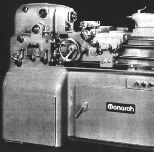
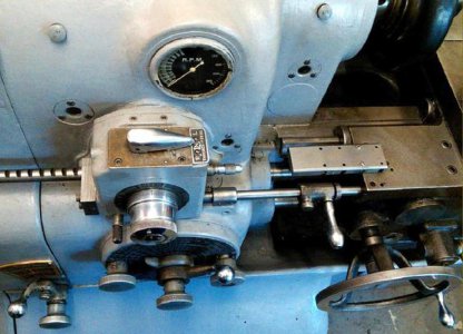
A later Model EE with the rectangular screwcutting chart on the face of the headstock.
Continued:
By 1945 the swing had increased a little to 12.5 inches and a longer bed was listed (which, surprisingly, did not prove popular) admitting 30 inches between centres. Modifications to the screwcutting gearbox resulted in an improvement to 50 feeds (from 0.0005" to 0.016") with the threading range extended to cover 60 threads from 3 to 184 t.p.i. In 1970 further mechanical modifications were made including the fitting of a combined English/Metric screwcutting gearbox and beautifully finished dual English/metric compound-feed dials. The English/metric gearbox could generate 60 English pitches from 3 to 184 t.p.i and 50 metric from 0.25 mm to 11 mm. With a standard spindle run-out of less than 40 millionths, and 30 millionths being an option (denoted by a headstock badge) the 113/32" bore headstock spindle runs in super-precision angular contact ABEC5 hand-matched, 60 mm ID bearings with the front being a non-standard and very expensive type fitted with a flange. The spindle is sleeved with an adaptor bush from its standard No. 12 Jarno to a No. 2 Morse taper and carries a 3"-D-1 Camlock nose with, as one useful option, an adapter unit containing an indexing gear and graduations to assist in the cutting of 2, 3, 4, 6, and 8 multi-start threads. Fitted with a substantial mechanical lock to ease the removal of chucks, the spindle is also provided with two safety devices: an electrical interlock to prevent it from running if accidentally engaged and a "Hi-lock" to prevent the engagement of backgear above 250 r.p.m. However, these features were only fitted on 'square-dial' machines, the 'round dial' having neither. Although the motor could be "plug reversed", that is, instantly changed from one direction of rotation to the other, this was also limited to no more than 250 r.p.m., a relay in the DC control box (called the anti-plug relay) pulling in and refusing reverse until the spindle stops.
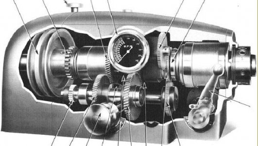
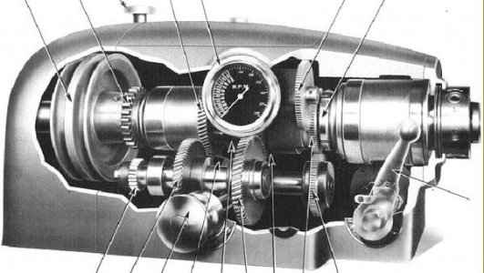
Spindle-speed ranges have varied over the years with the option, on earlier lathes, of either 25 to 2000 rpm, 40 to 4000 rpm and another with a maximum speed of 3500 r.p.m. (though just the higher set was available on later machines). There were no mechanical changes to the models, the only differences between them being the use of different diameter belt sheaves (pulleys) and recalibrated tachometers. All versions of the lathe have been fitted with the 5 : 1 reduction gearing that, on later lathes, gives 8 to 800 rpm; because the gearbox is mounted on the motor (in the cabinet base) the headstock spindle is completely isolated from whatever vibration effects the drive might create. On early lathes the headstock-mounted tachometer was mechanically driven by a gear on the spindle (the only gear in contact with it) and could read in forwards rotation only. Later models were given an improved electrical counter able to read with the spindle running backwards.
As a point of interest it is not recommended to increase the top speed on 'round dial' machines. These have a headstock divided into three compartments: one each for the front and rear bearings and one for the gearbox. The bearings are lubricated by the simple expedient of letting them sit, partially submerged, in a oil bath - a system adequate for slower running, but not for continuously high r.p.m.. Later revisions saw the headstock opened up into one cavity and a splash system, together with pipes, used to carry oil direct to the bearings. The leadscrew and its drive gears are used only for screwcutting - the power for sliding and surfacing feeds being fed from the headstock to the gearbox by a flat, endless belt, driven from the end of the headstock spindle and tensioned by a jockey pulley. In standard form (and bearing in mind the differences between the older and newer models) 60 English threads are available of: 3, 3.25, 3.5, 3.75, 4, 4.5, 5, 5.5, 5.75, 6, 6.5, 6.75, 7, 7.5, 8, 9, 10,11, 11.5, 12, 13, 13.5, 14, 15, 16, 18, 20, 22, 23, 24, 26, 27, 28, 30, 32, 36, 40, 44, 46, 48, 52, 54, 56, 60, 64, 72, 80, 88, 92, 96, 104, 108, 112, 120, 144, 160, 176 and 184 t.p.i. Carriage feed rates vary through fifty changes from 0.0005" to 0.016" per revolution of the headstock spindle. A combined English-metric gearbox was also built and offered as an optional extra. It is possible to cut metric threads on the ordinary lathe, but only by unbolting the cover over the automatically-lubricated gear train and substituting the appropriate translation gears.
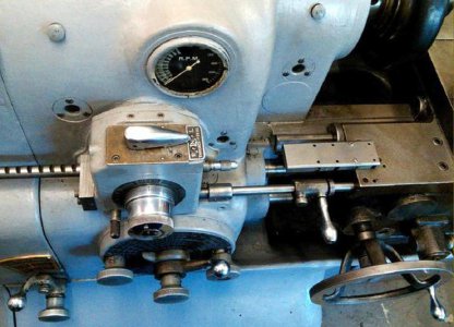
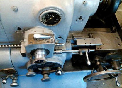
Some lathes have been found fitted with an ELSR (Electronic Leadscrew Reverse) threading system. These versions are easily recognised by a long rod running parallel to the top edge of the bed and their distinctly-different rectangular-form threading selector box on the front face of the headstock - this having, instead of just a dial selector on its front, a chrome-plated, left-to-right travel lever fitted on top. However, the ELSR was misleadingly named, for it did not actually reverse the leadscrew, its function was to provide a repeatable method of stopping the spindle at some chosen point for operations such as threading to a shoulder, or into the bottom of a blind hole, without the risk of over-running.
Instead of a headstock-mounted drum switch, a control rod was arranged to run from the threading selector housing through the top of the apron and from there to a support bracket fixed to the tailstock end of the bed. Keyed to the rod was a sliding motor-control lever, locked in place by a thumb-screw this acted as an adjustable stop. At the tailstock end the rod had a helical gear that turned on a white-metal bearing inside the support housing: moving the lever up and down caused the rod to slide left and right. At the headstock end the control rod had several grooves machined so as to form a circular rack, these engaging with a drum sporting two square cams off-set at 45° degrees to each other that operated, via a sliding rocker, forward and reverse micro-switches. There was also a small plunger fitted to the lower left of the threading control switch housing used as a safety device to lock the control rod in neutral and so avoid unexpected starts when working on the set-up. On top of the housing was a 3-position mechanical switch that slid the rocker (between the two square cams) to select left or right turning, or neutral, in which latter case neither cam was engaged and the spindle would not start. For normal turning and right-hand threading, the switch would be set to RIGHT. Pressing the control lever down caused the spindle to turn forwards and the carriage to move towards the headstock until it pushed on the lever and opened the contactor of the DC motor. The effect of opening the contactor was to bring into operation an electrical brake and this provided - if the same spindle speed was kept for all cuts- a repeatable stop. At low speed the system became even more effective and would give repeatability to within a fraction of a turn.
Continued below:
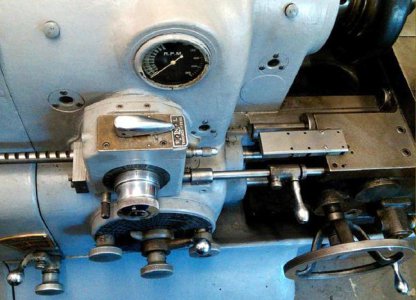
Lathes fitted with ELSR (Electronic Leadscrew Reverse) can be easily identified by a rectangular-form threading selector box with a chrome-plated, left-to-right travel lever fitted on top and a long rod running from headstock to tailstock with support at its far end in a curved bracket.
Continued:
For left-hand threading or feeds the leadscrew is reversed, in the usual way on the threading box and the switch set to LEFT - so reversing the operation of the control lever. Pressing the control lever down set the motor into reverse with the carriage still travelling towards the headstock, so that the control rod could stop the motor using the same method as for right-hand threads. Once the spindle had stopped, the tool was retracted and the spindle reversed - this bringing the carriage back to the start of the thread without the need to open the (oil-fed) leadscrew clasp nuts. Combined with the very useful 2-turn positive threading stop on the cross-slide screw, this arrangement made for a most efficient and accurate thread-cutting system.
A masterpiece of precision construction, the apron was carefully laid out for ease of use - though English readers may quibble about the positioning of the carriage-traverse handwheel at the left-hand side where the operator's hand can be showered with hot chippings. Power sliding and surfacing feeds are each selected by their own instant-action, lever-operated clutches: flicking a control up engages the feed with a downward motion to disengages it.
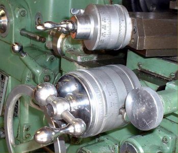
Of silken smoothness, the compound slide rest assembly was fitted with appropriately large and beautifully engraved dials that indicated the number of thousandths of an inch being taken off diameter - not the travel of the slide. The dials' chrome finish was softened by vapour blasting to give an anti-glare effect.
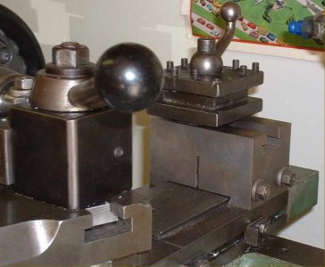
A wide range of accessories was offered and very few 10EEs came without a taper-turning attachment - the details of which varied: some having vernier scale adjusters with graduated dials - just like the English CVA lathe - others came with a "bolt-on" brass gear to turn. While a convenient and quick-to-operate telescoping cross-feed screw was available strangely, for this class of lathe, a fixed type was also supplied that required the screw to be removed before the unit could be brought into action. In addition to the usual fixed and travelling steadies, a variety of collets and collet holders, it was, at various times possible to specify dual inch/metric feed-screw dials, a rear dovetail and tool block on the cross slide, a (very rare) multi-position cross-feed micrometer stop and the previously-mentioned dual inch/metric screwcutting gearbox.
At times, compared with the greatly sought-after Hardinge HLV and HLV-H 12" x 20" toolroom lathe, the 10" EE Precision was (unaccountably) often underrated on the used market and available at a much more reasonable price. Today, with such a restricted choice of new machines, the market for this type of lathe is very much alive with a good trade in rebuilt machines and even new ones - United Airlines, for example, taking delivery of one in August 2000. Although a very heavy machine, at around 3250 lbs, it occupies a floor area of only 29" x 60" - and hence can be easily lost within a corner of the typical American domestic garage.
Although early production figures are difficult to determine (though the factory has records of every one made) since 1955 approximately 8,000 10EEs have been manufactured. In 1946 the base price was $4,194 but by 1955 had risen, with inflation, to $7,400 and reached $9,775 by 1965. Today (2008) they retail at $79,950 - the latter figure, adjusted against the retail prices index, shows it to be not as high as might be expected ($9,775 in 1965 being equal to approximately $59,373 in 2010).
Not only the general layout but also many detail features of the Monarch 10" EE lathe were incorporated in what was, in effect, a copy, the English CVA lathe.
A very rare capstan (screw-machine) version was also built, but in what must have been very small numbers..
*The following was kindly contributed by Mr. R. E. Hartzel of Marine and Industrial Engineering, Moorestown, New Jersey, USA
Monarch Lathe Electron Tube/Valve Control
There were two versions of electron tube/valve control. The early one used nine tubes/valves and the later used three. The workhorse of these controls is a thyatron tube/valve. The thyatron is constructed with three and sometimes four elements contained in a glass envelope mounted on a base with, in the smaller sizes, pins for connection into a socket. However, in the larger sizes, there is a top cap for connection to the plate or anode. In the case of the Cl 6J/5665 there are no pins, owing to the large currents through the unit, but flexible, insulated leads with bolt-on lugs known as "flying leads" Inside the glass envelope are the elements: i.e. heater or filament, the grid and the plate. Some tubes/valves contain a separate cathode close to the heater but most use the heater as the cathode. The heater is supplied with a voltage that causes it to come to a red heat and in doing so causes quantities of negative electrons to be emitted from its surface. The plate, being at a positive potential, exerts an attraction for these but the strongly negative grid between prevents the electrons from reaching the plate. At this point, if the negative grid voltage is reduced to zero and the grid voltage made ever so slightly positive, ionization will take place and the electrons will flow to the plate. The ionization within the glass envelope is enhanced by the presence of xenon gas and in some tubes/valves by mercury vapor - and in others by both. Once the tube/valve "strikes" it can only be stopped by opening the circuit to the anode/plate or when the alternating potential applied to the anode falls back to zero voltage if the grid is returned to a negative potential. In order to accomplish the foregoing, an alternating potential is used on the grid that can be shifted out of phase, or out of time, with respect to the phase or timing voltage applied to the anode. The foregoing imparts a pulsating flow of electrons between the cathode and the anode. The length or duration of the pulses results in a higher or lower value of alternating current being converted to direct or continuous current. This allows finite control of the output voltage resulting in finite speed control of a motor.
Applications for the thyatron have been found in many other areas including light dimmers and the control of electric furnaces and generators. In applying the thyatron to motor drives, there are other circuits which feedback a signal to the grid control circuit. One such circuit being that of sensing the reduction of speed owing to increased mechanical load. When this circuit senses a speed reduction, it feeds back a signal to the grid circuit, thereby compensating the speed loss. The response time of a thyatron is exceedingly fast and measured in microseconds. In conclusion, it would be remiss if I did not include what I consider to be the most important use known to myself of the thyatron, that being in the WWII code-breaking computer named Colossus. Tommy Flowers of the British Post Office Research Station at Dollis Hill, London, designed Colossus for use at Bletchley Park against the German Enigma codes. Tommy Flowers used thyatrons in place of electromechanical relays because their super-fast response time was superior - the need for speed being caused by the vast quantity of traffic to be processed. For those of you who are interested, there is a Bletchley Park web site and, most remarkably, a reconstructed Colossus has recently been installed in the museum..
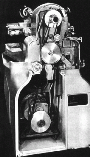
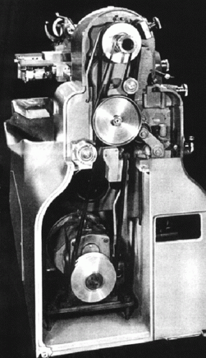
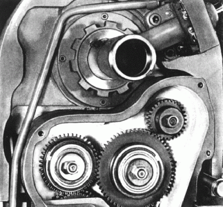
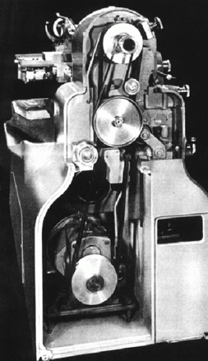
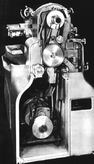
End covers removed showing the base-mounted DC motor and reduction gearbox and, at the top, the flat-belt drive system for the non-screwcutting feed to the gearbox.
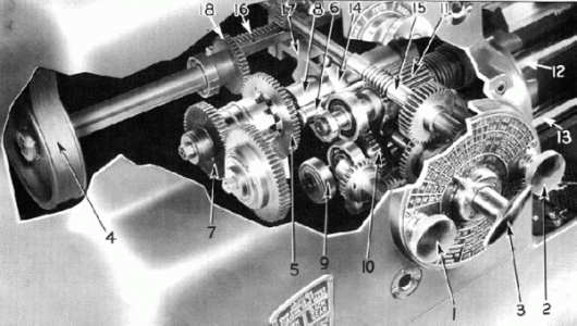
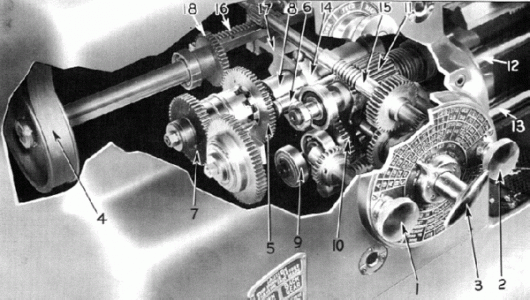
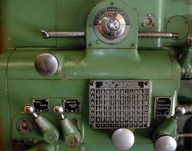
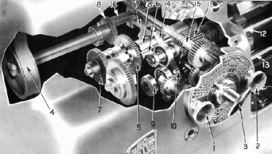
Complex and effective "Dial-in" screwcutting and feeds gearbox of the first Monarch EE Toolroom lathe.
Although dropped after a few years' production, this arrangement continued to be used on the very similar English CVA lathe. The threads were indicated on the top half of the Index Plate and feeds on the bottom. The gearbox was operated by the knobs 1 and 2, and the handle 3. To select feeds, the knob 2 was turned to the position marked "Feeds" and the knob 1 to any of the A, B or C "feed range" marked around its edge. The selector handle 3 was pushed in and turned to the desired feed shown on the Index Plate and then pulled out to lock the engagement. To select threads the knob in the vicinity of 4 (not shown) was moved to select left or right-hand threads. Knob 2 was set to the position marked "Threads" and knob 1 turned to the thread desired found within the ranges A, B or C marked on the upper half of the index plate. The selector handle 3 was pushed in and turned it until it pointed to the desired thread and then pulled out to lock it. Note the important information on the index plate concerning stud and gear positions on the gearbox drive train.
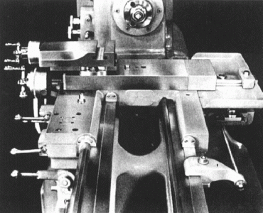
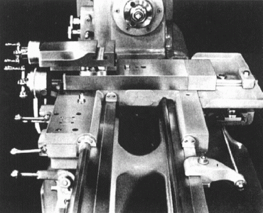
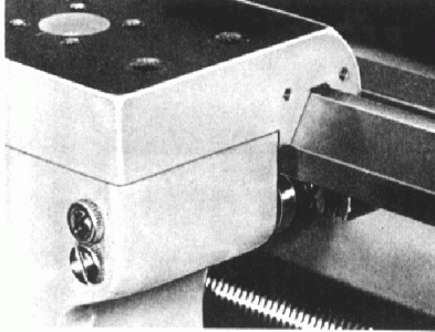
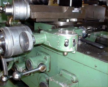
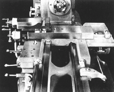
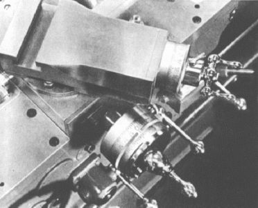
A basic test for a genuine toolroom lathe is that the width of the bed should be at least equal to, or greater than, the distance from it to the centre of the spindle. In addition, the EE has saddle arms which, at 20.5", are almost half the length of the bed ways; they are aligned by four ball bearing "gibs", mounted on eccentric studs, at the end of each arm - picture below.
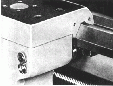
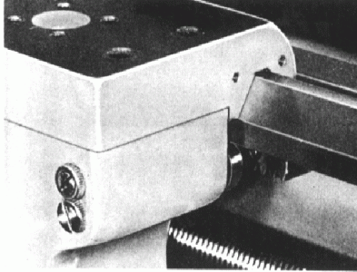
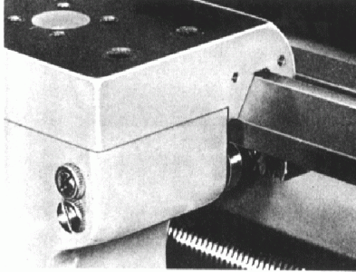
At the end of each saddle wing was a roller bearing which could be brought into contact with the underside of the bed by the adjustment of an eccentric screw.
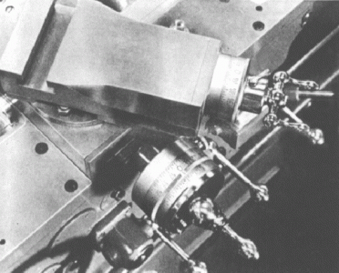
The micrometer dials were appropriately large and very clearly engraved with divisions that indicated the number of thousandths of an inch being taken off diameter. The dials' chrome finish was softened by vapour blasting to give an anti-glare effect.
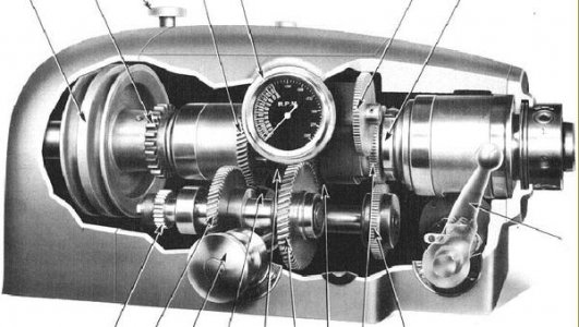
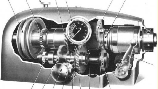
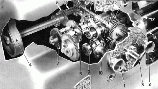
Cut-away view of an early (1940s) the Monarch EE headstock.
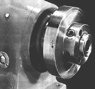
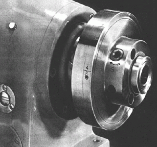
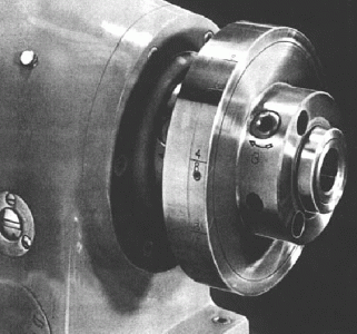
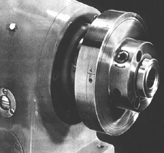
Headstock spindle fitted with the optional indexing unit for cutting multi-start threads.
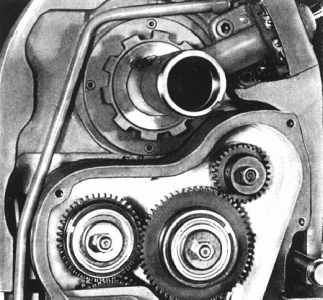
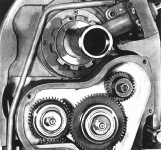
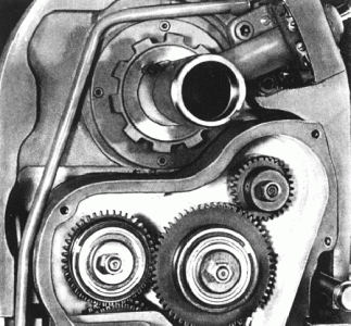
On all but the earliest machines the drive from headstock to screwcutting gearbox was totally enclosed and automatically lubricated. To cut metric threads the cover had to be unbolted and translation gears substituted for those already in place. An English-metric gearbox was offered as an optional extra.
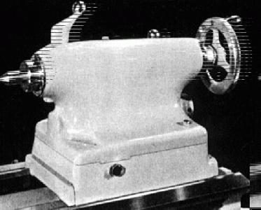
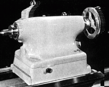
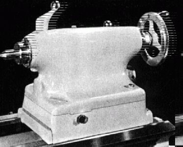
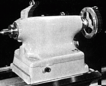
The set-over tailstock had a hardened, graduated spindle of 1.75" diameter with a travel of 3.5" The handwheel was fitted with a micrometer collar.
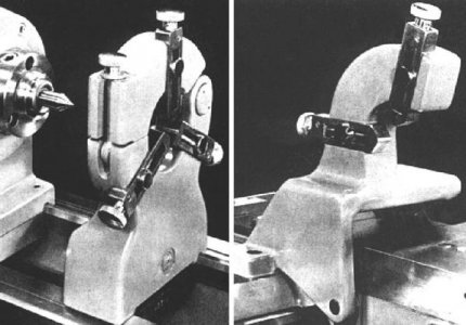
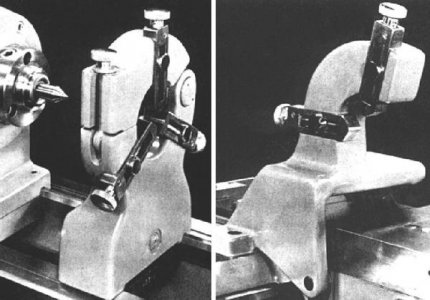
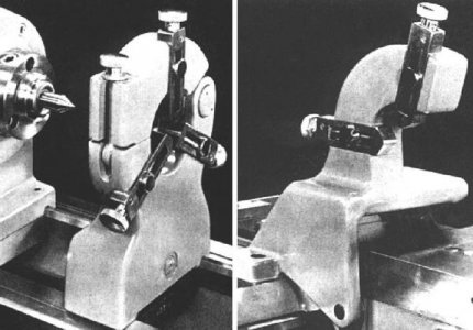
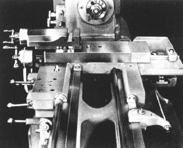
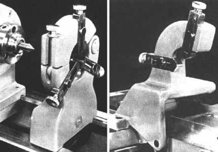
The rugged fixed steady (left) had a capacity of 3" and screw-adjusted bronze jaws. The travelling steady (right) was of unusual appearance - so now, if you ever find one at the bottom of a junk box, you'll now know exactly what you've discovered …...
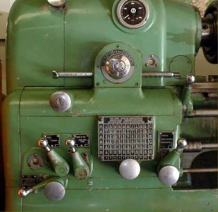
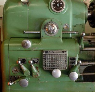
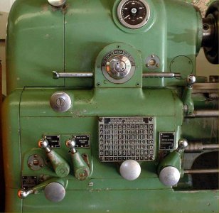
Dual inch/metric screwcutting gearbox
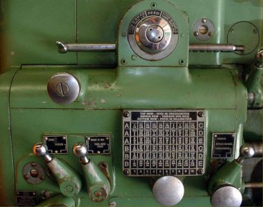
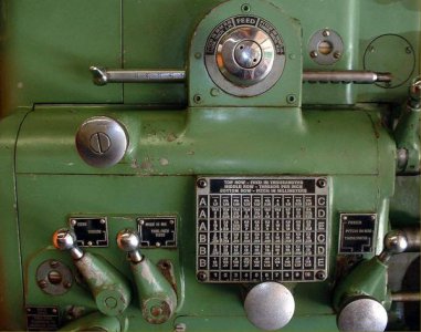
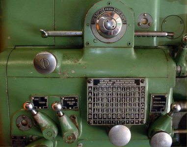
Dual inch/metric screwcutting gearbox chart
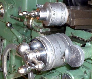
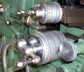
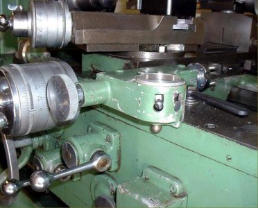
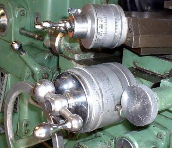
Superbly finished dual inch/metric micrometer dials
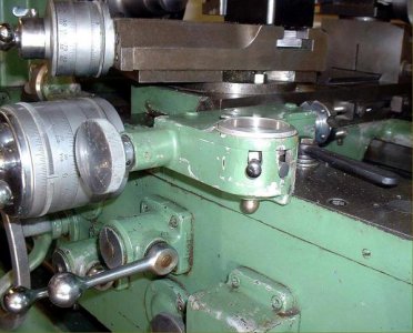
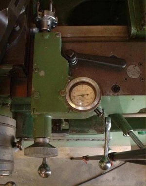
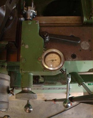
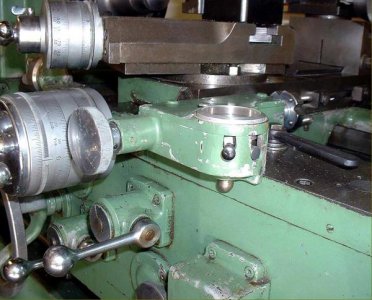
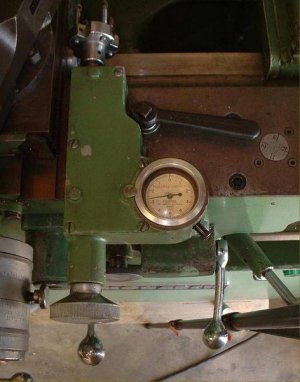
Above and below: the very rare (and highly effective) dial-gauge-set cross-feed limit stop
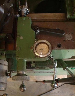
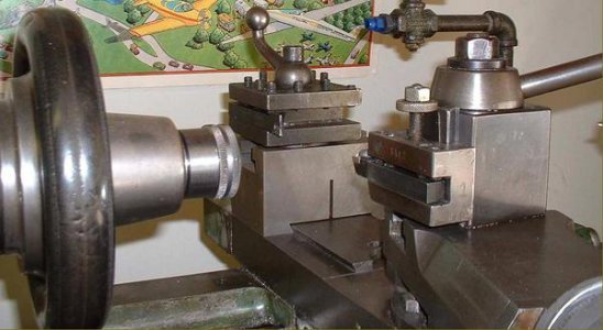
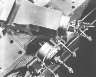
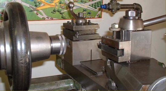
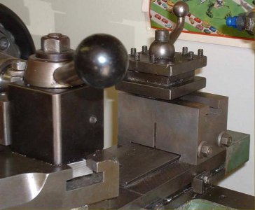
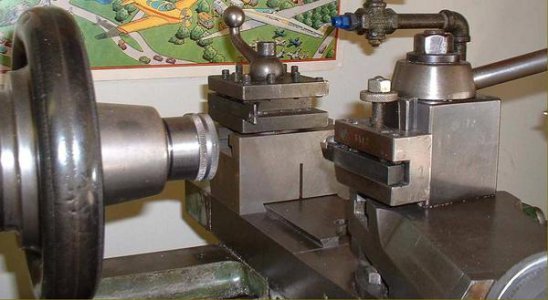
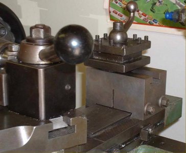
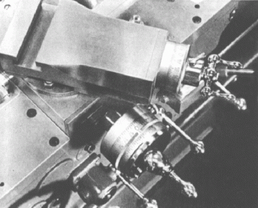
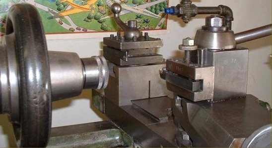
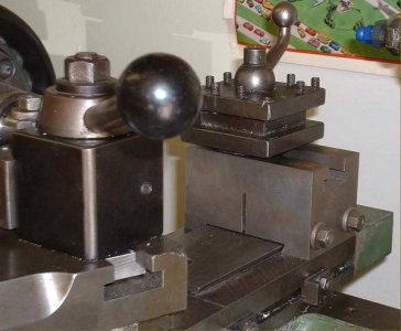
Above and below: the adjustable rear-mounted tool block
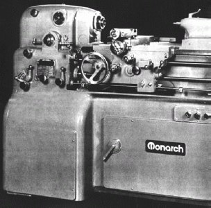
Introduced in 1939 with a 12 inch swing (not the 10 inches that its name would suggest) and a capacity of 20 inches between centres, today the Monarch 10EE Precision Toolroom lathe has a well-established reputation as one of the finest small lathes it is possible to buy. The first two examples produced,, with serial numbers EE-6156 and EE-6207/8, were shipped, respectively, to the Precision Scientific Company Chicago, IL and the Woodward Governor Company of Rockford, IL. The lathe followed and improved upon an already-established design path intended to produce the most accurate of work and the finest of surface finishes: the bed was mounted on a massive and heavy one-piece cast-iron stand with the entire drive system isolated inside and the headstock spindle turned by belt. The arrangement provided great stability and removed any chance of vibration from motors or gearboxes being transmitted to the workpiece. In addition, whenever sliding and surfacing feeds were selected (as distinct from gear-driven screwcutting) the precaution was taken of using a flat-belt to drive the gearbox - so isolating the drive from uneven gear impulses that might spoil the surface finish. Early machines, made until a change-over that lasted through 1944 and into 1945, are now referred to as the "old height" models and may be distinguished from later versions by the (beautifully-made) circular feeds-and-threading selector arrangement on the face of the gearbox. There were two types of "round" box: one used a rectangular knob that was pushed in and turned to select a gear range and another version where the ball lever was first rotated to disengage the gearbox, the centre wheel turned to select the range and then the ball lever turned again to re-engage the drive. One sub-version, the very rare ELSR, had a form of electronic leadscrew reverse incorporated, a fitting intended to speed up and make safe repetitive screwcutting operations. The screwcutting gearbox box was able to generate 30 different feeds from 0.001" to 0.0075" per revolution of the spindle and 50 combinations of threads from 3 to 92 t.p.i; a further distinguishing feature of these very early models was the open changewheel drive to the screwcutting gearbox - later lathes have the gears fully enclosed in an oil bath case. Although found very infrequently, it was possible to order a dual inch/metric screwcutting gearbox - an example is shown lower down this page.
As the lathe was very expensive it is likely that some customers would have ordered some changes to the specification, or had extra features included. One such, found on a 1942 example, was an unusual electrical reverse to the leadscrew. This mechanism was driven by a motor and gearbox, mounted above the ordinary screwcutting gearbox, together with a control rod that ran through the carriage to the tailstock end of the bed. Attached to the rod were collars that could be locked at any position--when the carriage struck a collar. the rod was pushed into the box and the drive reversed.
As early 10EEs were built during WW2, a shortage of materials and components caused their specification to vary slightly from month to month. While some, close together in serial number, had V-belt drive others had flat (though this may have been a customer preference); a number of different of DC control boxes were employed and variations around the complex drive system persisted for several years with the types coexisting side by side until a full change-over was completed. On the earliest machines the spindle was driven by a V or flat belt from a massive hydraulic/hydrostatic variable-speed unit of Sundstand manufacture that provided a speed range of 25 to 2500 rpm. In 1941 this was replaced by a three-phase motor driving a 3 h.p. DC generator that provided power for an electronic variable-speed drive system* - a not dissimilar arrangement also being used on the EnglishCromwell toolroom lathe. However, some experimentation appears to have been conducted by the factory (or a shortage of components encountered) as subsequent changes involved three versions of the Reliance VS Motor Generator unit, then a "WiaD" drive, a Module Drive and finally the Monarch DC type. Some details: in 1949, in line with new developments in electronics, the Reliance rotating motor-generator set (DC) arrangement was replaced by a system (WiaD) that used electronic-tube controlled thyratrons to rectify AC current to a variable DC voltage to drive a DC motor (multiple vacuum tubes being used to control the rectifier tubes). This set-up became better known as the "works in a drawer".In 1950/51 the drive was again redesigned and improved and then, in 1960, the WiaD superseded by fitting a more powerful 5 h.p. motor and a "module drive" that used an all-solid-state electronic module to control the electronic components (with the exception of the thyratrons); around 3,000 lathes were supplied with this system. In 1984 further alterations were made with an entirely solid-state DC armature regenerative drive replacing the now old-fashioned thyratron tubes and finally, in 1995, a change to one of the increasingly popular and less-expensive AC-inverter types that were finally ousting the DC models. By now the lathe was equipped as standard with a 7.5 HP AC TEFC motor - and this unit was also made available for field retrofits and factory rebuilding. Today, when a machine is factory refurbished, it will be fitted with either a 5 h.p. or 10 h.p. 3-phase motor - both having their speed varied by a modern inverter (VFD). For home-shop use the most convenient and reliable drives are the early Sundstrand, WiaD and Module types. A single-phase motor can be used to power the Sundstrand while both the WiaD and Module drives would have been be fitted with single-phase motors as standard when new. Only the coolant pump on the latter two types is 3-phase - and this can be run from a simple and inexpensive static converter. The motor generator units need to be powered from a proper rotary-phase converter (a static unit will be unhappy) while the Monarch Electronic DC drive will only run on a true 3-phase supply (either from the mains or a "phase-perfect" electronic phase converter). The drive motor (integral to the motor generator) is about 6.5 h.p. - a figure to use when working out the RPC size required. One unit recently tested with the MG unit was fitted with a 15 h.p. RPC and was pulling 20 amps at 240 volts out of the wall - and that was without the spindle running. It was promptly exchanged for an AC brushless servo drive. No matter what the system, all older electronic drive systems eventually prove troublesome and some recent successful conversions have been achieved by using a Baldor "Smart Motor" - though a small amount of machining is necessary to adapt the Baldor motor to the Monarch gearbox (including a spacer plate & spine shaft).
Continued below:

A later Model EE with the rectangular screwcutting chart on the face of the headstock.
Continued:
By 1945 the swing had increased a little to 12.5 inches and a longer bed was listed (which, surprisingly, did not prove popular) admitting 30 inches between centres. Modifications to the screwcutting gearbox resulted in an improvement to 50 feeds (from 0.0005" to 0.016") with the threading range extended to cover 60 threads from 3 to 184 t.p.i. In 1970 further mechanical modifications were made including the fitting of a combined English/Metric screwcutting gearbox and beautifully finished dual English/metric compound-feed dials. The English/metric gearbox could generate 60 English pitches from 3 to 184 t.p.i and 50 metric from 0.25 mm to 11 mm. With a standard spindle run-out of less than 40 millionths, and 30 millionths being an option (denoted by a headstock badge) the 113/32" bore headstock spindle runs in super-precision angular contact ABEC5 hand-matched, 60 mm ID bearings with the front being a non-standard and very expensive type fitted with a flange. The spindle is sleeved with an adaptor bush from its standard No. 12 Jarno to a No. 2 Morse taper and carries a 3"-D-1 Camlock nose with, as one useful option, an adapter unit containing an indexing gear and graduations to assist in the cutting of 2, 3, 4, 6, and 8 multi-start threads. Fitted with a substantial mechanical lock to ease the removal of chucks, the spindle is also provided with two safety devices: an electrical interlock to prevent it from running if accidentally engaged and a "Hi-lock" to prevent the engagement of backgear above 250 r.p.m. However, these features were only fitted on 'square-dial' machines, the 'round dial' having neither. Although the motor could be "plug reversed", that is, instantly changed from one direction of rotation to the other, this was also limited to no more than 250 r.p.m., a relay in the DC control box (called the anti-plug relay) pulling in and refusing reverse until the spindle stops.
Spindle-speed ranges have varied over the years with the option, on earlier lathes, of either 25 to 2000 rpm, 40 to 4000 rpm and another with a maximum speed of 3500 r.p.m. (though just the higher set was available on later machines). There were no mechanical changes to the models, the only differences between them being the use of different diameter belt sheaves (pulleys) and recalibrated tachometers. All versions of the lathe have been fitted with the 5 : 1 reduction gearing that, on later lathes, gives 8 to 800 rpm; because the gearbox is mounted on the motor (in the cabinet base) the headstock spindle is completely isolated from whatever vibration effects the drive might create. On early lathes the headstock-mounted tachometer was mechanically driven by a gear on the spindle (the only gear in contact with it) and could read in forwards rotation only. Later models were given an improved electrical counter able to read with the spindle running backwards.
As a point of interest it is not recommended to increase the top speed on 'round dial' machines. These have a headstock divided into three compartments: one each for the front and rear bearings and one for the gearbox. The bearings are lubricated by the simple expedient of letting them sit, partially submerged, in a oil bath - a system adequate for slower running, but not for continuously high r.p.m.. Later revisions saw the headstock opened up into one cavity and a splash system, together with pipes, used to carry oil direct to the bearings. The leadscrew and its drive gears are used only for screwcutting - the power for sliding and surfacing feeds being fed from the headstock to the gearbox by a flat, endless belt, driven from the end of the headstock spindle and tensioned by a jockey pulley. In standard form (and bearing in mind the differences between the older and newer models) 60 English threads are available of: 3, 3.25, 3.5, 3.75, 4, 4.5, 5, 5.5, 5.75, 6, 6.5, 6.75, 7, 7.5, 8, 9, 10,11, 11.5, 12, 13, 13.5, 14, 15, 16, 18, 20, 22, 23, 24, 26, 27, 28, 30, 32, 36, 40, 44, 46, 48, 52, 54, 56, 60, 64, 72, 80, 88, 92, 96, 104, 108, 112, 120, 144, 160, 176 and 184 t.p.i. Carriage feed rates vary through fifty changes from 0.0005" to 0.016" per revolution of the headstock spindle. A combined English-metric gearbox was also built and offered as an optional extra. It is possible to cut metric threads on the ordinary lathe, but only by unbolting the cover over the automatically-lubricated gear train and substituting the appropriate translation gears.
Some lathes have been found fitted with an ELSR (Electronic Leadscrew Reverse) threading system. These versions are easily recognised by a long rod running parallel to the top edge of the bed and their distinctly-different rectangular-form threading selector box on the front face of the headstock - this having, instead of just a dial selector on its front, a chrome-plated, left-to-right travel lever fitted on top. However, the ELSR was misleadingly named, for it did not actually reverse the leadscrew, its function was to provide a repeatable method of stopping the spindle at some chosen point for operations such as threading to a shoulder, or into the bottom of a blind hole, without the risk of over-running.
Instead of a headstock-mounted drum switch, a control rod was arranged to run from the threading selector housing through the top of the apron and from there to a support bracket fixed to the tailstock end of the bed. Keyed to the rod was a sliding motor-control lever, locked in place by a thumb-screw this acted as an adjustable stop. At the tailstock end the rod had a helical gear that turned on a white-metal bearing inside the support housing: moving the lever up and down caused the rod to slide left and right. At the headstock end the control rod had several grooves machined so as to form a circular rack, these engaging with a drum sporting two square cams off-set at 45° degrees to each other that operated, via a sliding rocker, forward and reverse micro-switches. There was also a small plunger fitted to the lower left of the threading control switch housing used as a safety device to lock the control rod in neutral and so avoid unexpected starts when working on the set-up. On top of the housing was a 3-position mechanical switch that slid the rocker (between the two square cams) to select left or right turning, or neutral, in which latter case neither cam was engaged and the spindle would not start. For normal turning and right-hand threading, the switch would be set to RIGHT. Pressing the control lever down caused the spindle to turn forwards and the carriage to move towards the headstock until it pushed on the lever and opened the contactor of the DC motor. The effect of opening the contactor was to bring into operation an electrical brake and this provided - if the same spindle speed was kept for all cuts- a repeatable stop. At low speed the system became even more effective and would give repeatability to within a fraction of a turn.
Continued below:

Lathes fitted with ELSR (Electronic Leadscrew Reverse) can be easily identified by a rectangular-form threading selector box with a chrome-plated, left-to-right travel lever fitted on top and a long rod running from headstock to tailstock with support at its far end in a curved bracket.
Continued:
For left-hand threading or feeds the leadscrew is reversed, in the usual way on the threading box and the switch set to LEFT - so reversing the operation of the control lever. Pressing the control lever down set the motor into reverse with the carriage still travelling towards the headstock, so that the control rod could stop the motor using the same method as for right-hand threads. Once the spindle had stopped, the tool was retracted and the spindle reversed - this bringing the carriage back to the start of the thread without the need to open the (oil-fed) leadscrew clasp nuts. Combined with the very useful 2-turn positive threading stop on the cross-slide screw, this arrangement made for a most efficient and accurate thread-cutting system.
A masterpiece of precision construction, the apron was carefully laid out for ease of use - though English readers may quibble about the positioning of the carriage-traverse handwheel at the left-hand side where the operator's hand can be showered with hot chippings. Power sliding and surfacing feeds are each selected by their own instant-action, lever-operated clutches: flicking a control up engages the feed with a downward motion to disengages it.
Of silken smoothness, the compound slide rest assembly was fitted with appropriately large and beautifully engraved dials that indicated the number of thousandths of an inch being taken off diameter - not the travel of the slide. The dials' chrome finish was softened by vapour blasting to give an anti-glare effect.
A wide range of accessories was offered and very few 10EEs came without a taper-turning attachment - the details of which varied: some having vernier scale adjusters with graduated dials - just like the English CVA lathe - others came with a "bolt-on" brass gear to turn. While a convenient and quick-to-operate telescoping cross-feed screw was available strangely, for this class of lathe, a fixed type was also supplied that required the screw to be removed before the unit could be brought into action. In addition to the usual fixed and travelling steadies, a variety of collets and collet holders, it was, at various times possible to specify dual inch/metric feed-screw dials, a rear dovetail and tool block on the cross slide, a (very rare) multi-position cross-feed micrometer stop and the previously-mentioned dual inch/metric screwcutting gearbox.
At times, compared with the greatly sought-after Hardinge HLV and HLV-H 12" x 20" toolroom lathe, the 10" EE Precision was (unaccountably) often underrated on the used market and available at a much more reasonable price. Today, with such a restricted choice of new machines, the market for this type of lathe is very much alive with a good trade in rebuilt machines and even new ones - United Airlines, for example, taking delivery of one in August 2000. Although a very heavy machine, at around 3250 lbs, it occupies a floor area of only 29" x 60" - and hence can be easily lost within a corner of the typical American domestic garage.
Although early production figures are difficult to determine (though the factory has records of every one made) since 1955 approximately 8,000 10EEs have been manufactured. In 1946 the base price was $4,194 but by 1955 had risen, with inflation, to $7,400 and reached $9,775 by 1965. Today (2008) they retail at $79,950 - the latter figure, adjusted against the retail prices index, shows it to be not as high as might be expected ($9,775 in 1965 being equal to approximately $59,373 in 2010).
Not only the general layout but also many detail features of the Monarch 10" EE lathe were incorporated in what was, in effect, a copy, the English CVA lathe.
A very rare capstan (screw-machine) version was also built, but in what must have been very small numbers..
*The following was kindly contributed by Mr. R. E. Hartzel of Marine and Industrial Engineering, Moorestown, New Jersey, USA
Monarch Lathe Electron Tube/Valve Control
There were two versions of electron tube/valve control. The early one used nine tubes/valves and the later used three. The workhorse of these controls is a thyatron tube/valve. The thyatron is constructed with three and sometimes four elements contained in a glass envelope mounted on a base with, in the smaller sizes, pins for connection into a socket. However, in the larger sizes, there is a top cap for connection to the plate or anode. In the case of the Cl 6J/5665 there are no pins, owing to the large currents through the unit, but flexible, insulated leads with bolt-on lugs known as "flying leads" Inside the glass envelope are the elements: i.e. heater or filament, the grid and the plate. Some tubes/valves contain a separate cathode close to the heater but most use the heater as the cathode. The heater is supplied with a voltage that causes it to come to a red heat and in doing so causes quantities of negative electrons to be emitted from its surface. The plate, being at a positive potential, exerts an attraction for these but the strongly negative grid between prevents the electrons from reaching the plate. At this point, if the negative grid voltage is reduced to zero and the grid voltage made ever so slightly positive, ionization will take place and the electrons will flow to the plate. The ionization within the glass envelope is enhanced by the presence of xenon gas and in some tubes/valves by mercury vapor - and in others by both. Once the tube/valve "strikes" it can only be stopped by opening the circuit to the anode/plate or when the alternating potential applied to the anode falls back to zero voltage if the grid is returned to a negative potential. In order to accomplish the foregoing, an alternating potential is used on the grid that can be shifted out of phase, or out of time, with respect to the phase or timing voltage applied to the anode. The foregoing imparts a pulsating flow of electrons between the cathode and the anode. The length or duration of the pulses results in a higher or lower value of alternating current being converted to direct or continuous current. This allows finite control of the output voltage resulting in finite speed control of a motor.
Applications for the thyatron have been found in many other areas including light dimmers and the control of electric furnaces and generators. In applying the thyatron to motor drives, there are other circuits which feedback a signal to the grid control circuit. One such circuit being that of sensing the reduction of speed owing to increased mechanical load. When this circuit senses a speed reduction, it feeds back a signal to the grid circuit, thereby compensating the speed loss. The response time of a thyatron is exceedingly fast and measured in microseconds. In conclusion, it would be remiss if I did not include what I consider to be the most important use known to myself of the thyatron, that being in the WWII code-breaking computer named Colossus. Tommy Flowers of the British Post Office Research Station at Dollis Hill, London, designed Colossus for use at Bletchley Park against the German Enigma codes. Tommy Flowers used thyatrons in place of electromechanical relays because their super-fast response time was superior - the need for speed being caused by the vast quantity of traffic to be processed. For those of you who are interested, there is a Bletchley Park web site and, most remarkably, a reconstructed Colossus has recently been installed in the museum..

End covers removed showing the base-mounted DC motor and reduction gearbox and, at the top, the flat-belt drive system for the non-screwcutting feed to the gearbox.

Complex and effective "Dial-in" screwcutting and feeds gearbox of the first Monarch EE Toolroom lathe.
Although dropped after a few years' production, this arrangement continued to be used on the very similar English CVA lathe. The threads were indicated on the top half of the Index Plate and feeds on the bottom. The gearbox was operated by the knobs 1 and 2, and the handle 3. To select feeds, the knob 2 was turned to the position marked "Feeds" and the knob 1 to any of the A, B or C "feed range" marked around its edge. The selector handle 3 was pushed in and turned to the desired feed shown on the Index Plate and then pulled out to lock the engagement. To select threads the knob in the vicinity of 4 (not shown) was moved to select left or right-hand threads. Knob 2 was set to the position marked "Threads" and knob 1 turned to the thread desired found within the ranges A, B or C marked on the upper half of the index plate. The selector handle 3 was pushed in and turned it until it pointed to the desired thread and then pulled out to lock it. Note the important information on the index plate concerning stud and gear positions on the gearbox drive train.

A basic test for a genuine toolroom lathe is that the width of the bed should be at least equal to, or greater than, the distance from it to the centre of the spindle. In addition, the EE has saddle arms which, at 20.5", are almost half the length of the bed ways; they are aligned by four ball bearing "gibs", mounted on eccentric studs, at the end of each arm - picture below.

At the end of each saddle wing was a roller bearing which could be brought into contact with the underside of the bed by the adjustment of an eccentric screw.

The micrometer dials were appropriately large and very clearly engraved with divisions that indicated the number of thousandths of an inch being taken off diameter. The dials' chrome finish was softened by vapour blasting to give an anti-glare effect.

Cut-away view of an early (1940s) the Monarch EE headstock.

Headstock spindle fitted with the optional indexing unit for cutting multi-start threads.

On all but the earliest machines the drive from headstock to screwcutting gearbox was totally enclosed and automatically lubricated. To cut metric threads the cover had to be unbolted and translation gears substituted for those already in place. An English-metric gearbox was offered as an optional extra.

The set-over tailstock had a hardened, graduated spindle of 1.75" diameter with a travel of 3.5" The handwheel was fitted with a micrometer collar.

The rugged fixed steady (left) had a capacity of 3" and screw-adjusted bronze jaws. The travelling steady (right) was of unusual appearance - so now, if you ever find one at the bottom of a junk box, you'll now know exactly what you've discovered …...

Dual inch/metric screwcutting gearbox

Dual inch/metric screwcutting gearbox chart

Superbly finished dual inch/metric micrometer dials

Above and below: the very rare (and highly effective) dial-gauge-set cross-feed limit stop


Above and below: the adjustable rear-mounted tool block


