Modeling A Slit in Fusion 360

wnchstrtnfldvlle

H-M Supporter - Gold Member
H-M Supporter Gold Member
Joined
Oct 12, 2023
Messages
138
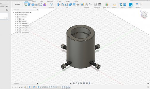
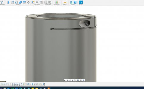
So I am working on modeling a lathe spider, both for practice with CAD and to make drawings to take down to the shop so I'm not just winging it as I go. I am new to the software, and have just been googling what I am trying to accomplish and following the tutorials on YouTube. But I'm not having much luck for this step. Any suggestions on where to start would be awesome. Pics included for clarity. Also, I'm thinking it would be better to model the threaded hole and counterbore before the slit. Would you all agree?
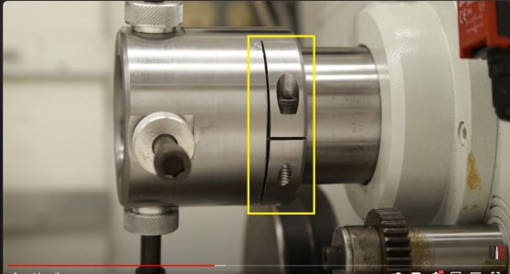
Screenshot.jpg

What I have so far
Fusion 360 Screenshot.jpg
 
Those two slits can be extrusions. For the one normal to the cylinder axis, create an offset plane from the cylinder’s end face, and then sketch on that plane and project from the cylinder’s features. For the one normal to the clamp bolt, you should be able to sketch on an existing plane.
 
I'm not an expert with Fusion myself. I'm not sure it would matter which feature you model first. In operation I would cut the counter bore and threads before slitting. But I'm not sure it would matter on the drawing.

I agree with @jwmelvin on the drawing.
 
You could do it with a single plane (assuming the radial slit goes half-way through the work) using any plane that contains the axis of the cylinder. Draw your 'T' shape, then extrude (cut) outward. Then pick a plan at right angles to that one to do the bolt hole.

GsT
 
Back
Top