Missing and Broken Gears for Lathe

BruceNorEast

Registered
Registered
Joined
Sep 6, 2013
Messages
8
My lathe has a broken worm-wheel gear for the power feed, and is also missing a gear and a shaft inside the apron.

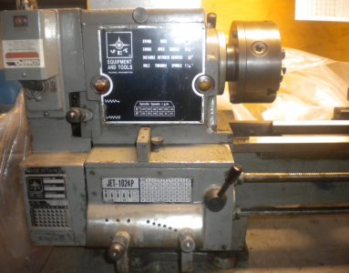
It's a Jet 1024P (10") lathe, made in Taiwan in the 1980s (I think). I got it used from a factory that was closing, no information is available from the source. The manufacturer does not have any information, but I did find a couple of PDFs for the manual searching online - neither is exactly my machine, but close in most areas except the apron.

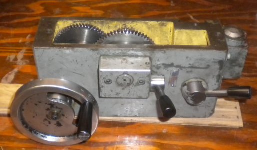
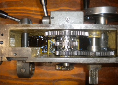
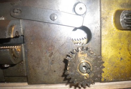
I'm not terribly worried about the brass worm wheel gear; fixing or replacing / making a replacement isn't too bad when you have the original part in hand. But the missing parts have been a show stopper. Best I can tell, it was some kind of idler gear and shaft (mounted between the lower shaft that's connected to the worm, and the clutch power feed gears - notice the space and hole in this area in the attached photos).

The parts diagrams from the manuals I've looked at don't show this assembly. It appears that the worm wheel gear shaft on mine is mounted much lower than others, resulting in a large gap - where an idler probably existed.

One thing that's really confused me here is that all of the other shafts have substantial support on both ends, yet the idler is supported on one end only without any shoulder from the casting (the casting wall is at its thinnest in this area). It appears like a design flaw on my model, that the other manuals show corrected (by moving all the worm parts up so the drive gear contacts the clutch gear).

I'd appreciate hearing anything helpful that you may think of.
Bruce.
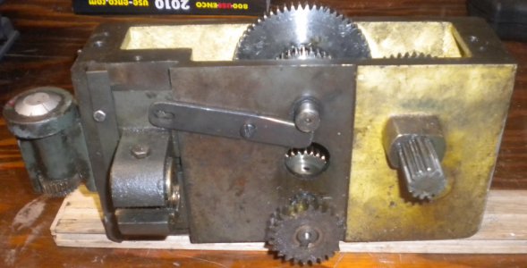
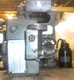
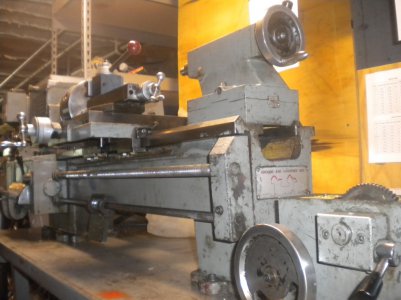
ApronBack.jpg ApronFront.jpg ApronInside.jpg ApronSide.jpg ApronTop.jpg
 
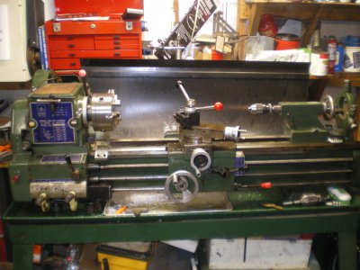
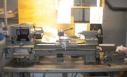
You should also post a few pictures of the complete lathe as there were so many styles made and exact copies but sold by several companies. You might get lucky if the design is the same. Attach some more pictures. It looks like it's the power transfer gear that runs the cross feed or saddle feed from the worm wheel on the outside of the saddle right? Rich
 
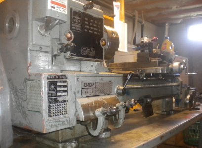
A close up of the plate on the end of the apron might provide a clue or two.

The apron may have been a transplant from a different, but similar machine.

I am not getting enough detail of the operation from the pictures, but have you considered that everything is there, just not assembled correctly?

Ray
 
On the outside it appears very similar to my jet 1236 and it's 1024 cousin (share the same manual). Mine was made 6/83 and has a different feed selector lever, that I suspect came later than yours with mechanical lockout to prevent engaging both the feed and half nuts at the same time. I'm thinking yours is earlier and mine came from modified castings. Yours has more gears than I recall in mine.

IMGP2935.JPG

I have been searching for dis-assembled pics of mine but no luck finding them. I may not have taken any.

The manual for mine is in the downloads of this forum.

Steve

IMGP2935.JPG
 
Hey Guys, thanks for the quick response.

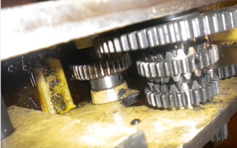
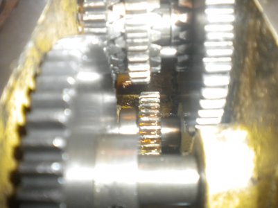
Richard, there must have been a transfer or idler gear that went between the worm wheel shaft and the power feed gear shaft. If you looks at photo "ApronGears" (the second of the new images), it's looking from the headstock side down into the apron. The first/large gear on the left is on the shaft that drives the carriage. The large gear on the top-right drives the crossfeed. The gear next to that is the clutch gear; center is neutral, it's currently in the carriage drive position - engaged with the leftmost gear which is also engaged with the large gear on the left. But the drive gear, shown at the bottom is too far from the clutch gear above to do anything, it just spins freely. The drive gear is on a shaft that comes out the back of the apron and has the worm wheel on it.

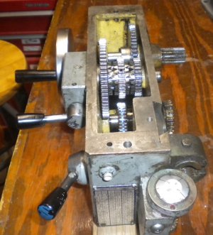
Ray, I've attached more photos, but I'm not sure if they'll help much. It does not look like there are parts from different machines here, everything lines up - there's just a missing object between the worm-wheel-shaft drive gear (on the bottom) and the clutch gear above it at the top. The worm gear rides a slotted shaft and is held in place by a plate that mounts to the bottom of the apron. It looks like other models have this attached to the back. This increases the distance between the shafts, apparently requiring an idler. There's no way that the existing shafts and gears go anyplace else than where they are, it's simply that something is missing. My guess is that someone crashed it, and the idler assembly came loose inside, possibly binding up when attempting to move the carriage manually - so someone took it out and left it that way.

Steve, at first glance it does seem similar to your lathe. But you have three shafts where I have only two, and the spacing between them on mine seems larger. The upper half-nut threading shaft is about halfway up the back of my apron, while the slotted power feed shaft is right about at the bottom. I don't think yours needs an idler like mine does, to bridge the extra distance/gap between gears.

Please note that the view from the back that shows the missing parts mounting hole is deceiving; it may seem that the distance between the gears is slight, but these gears are not aligned vertically - the bottom one is driven from the broken worm wheel seen in the foreground, but the upper gear is the crossfeed drive gear. The clutch gear that is aligned vertically can not be seen in this shot. Also note the interlock lever (that prevents the power feed from being moved out of neutral when the half-nuts are engaged) is partially blocking the hole, so any external support can only go up part of the way to allow the interlock lever free movement. This added to the confusion when I was trying to figure out what's missing, thinking maybe a plastic plug went there. But there's no getting around the need for an idler to transfer the power from the lower gear to the upper, unless maybe it was a belt? As lousy as it is (in my mind anyway), it had to have been an idler with a press fit shaft going into that hole, unsupported on the other end. Yuck!

Bruce.

LathHeadstockView.jpg ApronGears.jpg ApronBackHoleView.jpg ApronSideDialEnd.jpg LathTailstockEndView.jpg LathHeadstockFront.jpg LathFrontApronOff.jpg
 
Hey Guys, thanks for the quick response.


Steve, at first glance it does seem similar to your lathe. But you have three shafts where I have only two, and the spacing between them on mine seems larger. The upper half-nut threading shaft is about halfway up the back of my apron, while the slotted power feed shaft is right about at the bottom. I don't think yours needs an idler like mine does, to bridge the extra distance/gap between gears.


Bruce.

Bruce, that 3rd shaft is the fwd/off/rev switch rod since mine is the "S" model. It pretty much just passes behind the apron. Anyhow the lead screw and slotted shaft are ~ 2 1/4" CL to CL


Steve

- - - Updated - - -

oh, the link to the manual I mentioned is http://www.hobby-machinist.com/vbdownloads.php?do=download&downloadid=241 if you didn't find it already.

Steve
 
Hello Bruce

I have the same problem with my lathe. Friday I was at work and suddenly my cross slide remained stationary. All the teeth of the worm gear were worn away. Today I phoned my supplier for a replacement part. He promised me that I would receive a new part at the end of the week. What we can do is, I measure the new worm gear and compare it with the size of your worm gear. When that is the same there is no problem to get a replacement part for your lathe.

My email address is gemonds@scarlet.be

I hope it will succeed
Gerard
 
Bruce, that 3rd shaft is the fwd/off/rev switch rod since mine is the "S" model. It pretty much just passes behind the apron. Anyhow the lead screw and slotted shaft are ~ 2 1/4" CL to CL

Steve

- - - Updated - - -

oh, the link to the manual I mentioned is http://www.hobby-machinist.com/vbdownloads.php?do=download&downloadid=241 if you didn't find it already.

Steve

Hi Steve, thanks for the link and info, I do appreciate your efforts.

I seem to be too new here to access the manual (lacking permission to the downloads section), but I'll keep trying.

Did a quick look with a ruler, mine is very close to 3" CL to CL.

Any thoughts on how to create a replacement gear without the original? (with just the two remaining gears that it should connect with to go by) As you can see in the images, it's difficult to measure between the gears inside the apron. I'll measure the distance between centers of the two remaining shafts and then remove them to measure the gears.


Hello Gerard, thank you for your kind offer to help with a replacement worm wheel gear.

But my main problem is not the damaged brass worm wheel, but rather the missing gear and shaft inside the apron.

And please note that I am just guessing that's what's missing based on nothing more than inspecting the remaining apron assembly - I could be way off.

Good luck to you!
Bruce.
 
Hard to tell from the pictures, but it looks to me like the gear on the worm wheel shaft is different pitch than the clutch gear, which would mean that the idler would be compound (2 gears sandwiched together) gear.


Ray
 
Hi Bruce

I think the missing gear will not be a problem and I think I can help you. I have a lot of experience whit gears and making gears.
Have a look on the project "shaper" on my site

http://home.scarlet.be/mini-draaien-frezen

I have some drawings of the apron but I can't attaches them in this message. Can you send me your private e-mail
address so I can send them to you, or can you explain how I can attaches pictures in this message.

Because it is a machine that is made in Taiwan I suppose it is made in metric sizes. Then, the gears are also metric gears.
First you must determine the module of the gears. You do this by dividing the outside diameter of a gear by
the number of teeth + 2. You obtain a number 1 or 1.25 or 1.5. I think in this case it will not be greater.
Measure the distance between centers of the two shafts. Then it is possible to calculate the number of teeth of the
missing gear, no problem.
Once you have received the drawings we can easily correspond about it and tell you what you have to do.

Sorry for my linguistic blunders. I'm normally Dutch speaking.

Gerard
 
Last edited:
Back
Top