- Joined
- Jan 8, 2016
- Messages
- 171
Mini Lathe Slide Screw Mod
(C) Copyright 2016
I was motivated to design this mod because the compound slide on my machine suffered from runout originating in the screw assembly which I found unacceptable and unnecessary. Wear and/or poorly manufactured parts made it so tightening the bolt all the way did not resolve the issue. Adding shims to remove runout removed the runout, but the screw assembly became difficult to turn.
This mod works amazingly well. I can now adjust the compound slide by pressing a fingertip on the end of the handle, and there is no runout in the screw assembly.
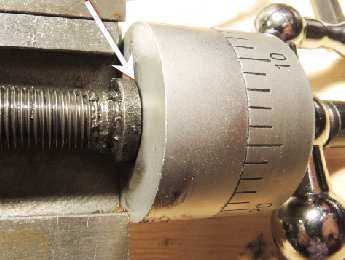
This is a fairly extensive compound screw mod and requires a bit of machining fun. So why go to the trouble? Well, the factory issue doesn’t work very well do to poor design and it is manufactured to be inexpensive; lacking bearings or even sleeve bushings. The assembly is either prone to runout or binds and does not rotate smoothly and easily. There are multiple steps, but the mod is not difficult to do and the total cost is less than $10.00 US.
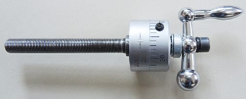
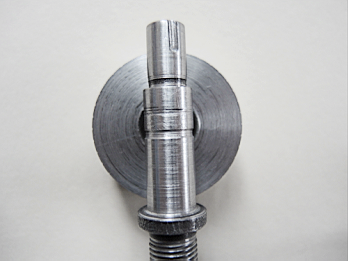
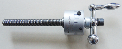
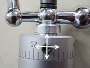
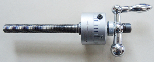
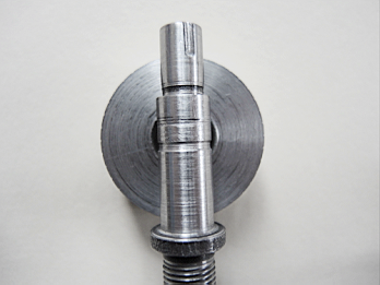
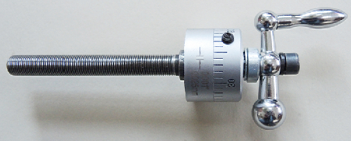
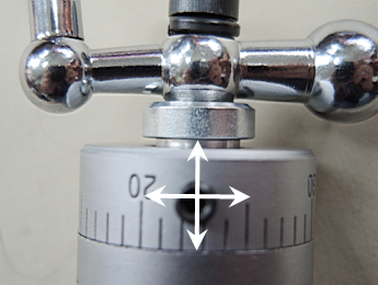
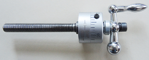
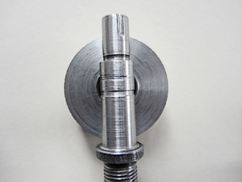
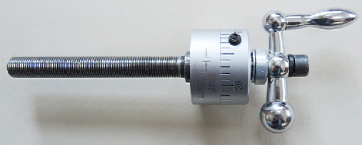
With this mod, 100% of runout is removed, and it rotates so smoothly it can actually be rotated with a feather. This is not an exaggeration. There is zero runout, and when the assembly is held by the retainer as pictured below, gently tapping the handle off its apogee causes the handle to continue to rotate most of the way to the bottom under its own weight.
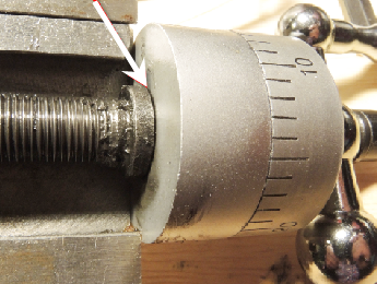
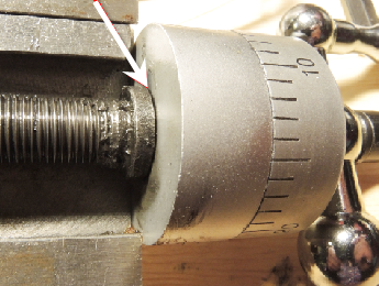
That being said, there is another mod out there that utilizes one large bearing between the retainer and the dial, (reference below image), is considerably simpler to make and resolves 90% of the problems associated with the screw assembly. You may be completely satisfied with that mod. This mod adds two additional improvements by adding an additional bearing between the flange and the retainer, and it completely removes the dial as a component that must be compressed between the other components to remove runout.
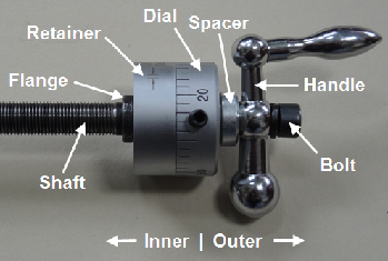
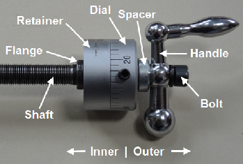
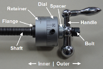
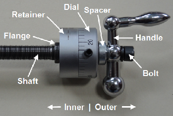
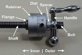
To understand this unique mod, it is necessary to understand exactly how the screw assembly works, so please be patient with this introduction. Once understood, the design deficiencies and how to remedy them are apparent. For clarity, the following terms will be used consistently throughout these instructions.
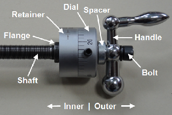
Cause of runout or binding:
All the components are held between the bolt and flange. There is a small lip at the top of the outer edge of the bore in the handle, so the handle is not free to slide completely down the shaft. As the bolt is tightened, the other pieces slide down the shaft towards the flange until the outer end of the shaft reaches the lip at the outer edge in the handle bore. The bolt then simply tightens the handle to the shaft. With the handle secure to the shaft, the inner edge of the handle is a fixed distance from the flange. All of the components now must exist in this defined area between the flange and the inner edge of the handle.
Under ideal conditions, because the components are sized to fit in the defined area this sort of works, but not all that well, and is prone to failure. It fails when wear is introduced between the flange and the retainer, or the retainer and the dial, or the dial and the spacer. If any of these parts become worn, nonadjustable runout is introduced into the system because the components can slide on the shaft between the flange and the inner edge of the handle.
Inherent design flaws:
Because the shaft and all parts starting with the dial outward must be free to rotate, runout is in fact not only necessary but is designed in! There MUST be some slop so the components are free to move. If a shim is introduced between the flange and the retainer or the dial and the spacer, when bolt is tightened to remove all runout the mechanism locks up or binds, resulting in compromised ease of rotation.
Yet another design flaw is that in order to remove runout, the dial must press against the outer surface of the retainer, but the dial must be free to rotate separately from the shaft and the rest of the components so that it may be zeroed out. If the assembly is tightened enough to remove all runout, the inner dial surface binds against the outer surface of the retainer. Even if the two surfaces are lubricated it compromises ease of rotation.
This mod fully addresses the aforementioned problems.
Now, finally… On with the mod!
Parts and tools needed:
1. (2) 10 mm x 15 mm x 4 mm bearings. I picked up four from Amazon for $7.99 with free shipping. Enough for both the cross and compound slides.
2. (1) 5 mm set screw. $0.43
3. (1) 4” piece of ½” aluminum bar stock
4. 4.5 mm drill bit
5. 5 mm tap
6. 10 mm drill bit. I used a 25/64” (9.92 mm) bit. It was so close to 10 mm that a little sand paper finished the job.
7. 4 mm length nylon trimmer line or tiny chunk of plastic, Delrin , thermoplastic or the like. $0.00
8. Rotary tool with a burr bit or milling machine
9. Sturdy paper clip or a small finishing nail, etc.
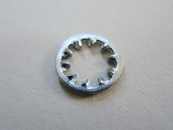
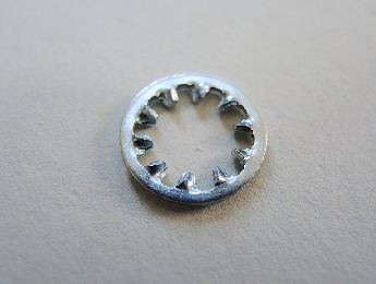
10. (1) 8 mm or 5/16” internal tooth lock washer. Easily found at a hardware store for about $0.20.
Of course the SAE equivalently sized set screw, drill and tap could be substituted if that is what you have on hand.
Step 1: Install retainer bearings
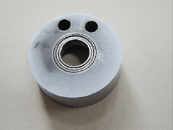
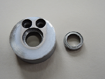
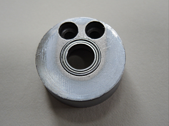
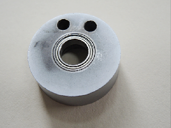
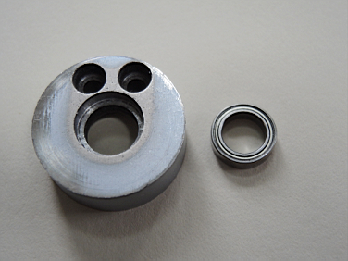
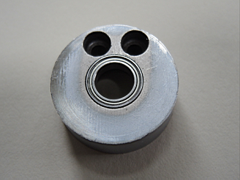
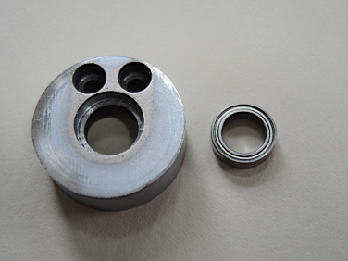
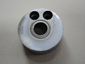
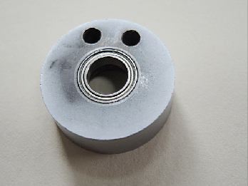
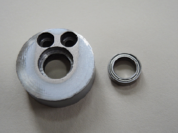
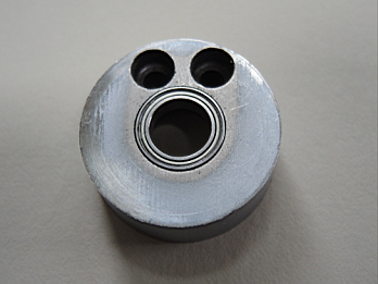
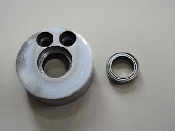
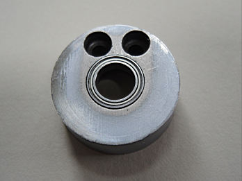
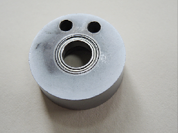
Machine both sides of the retainer to accept the bearings to be flush with the retainer surface.
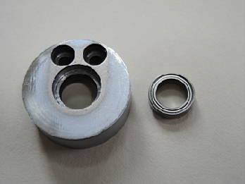
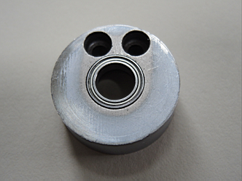
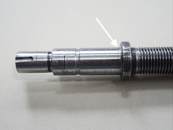
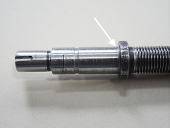
Step 2: Reduce shaft diameter
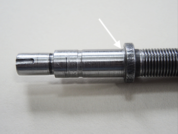
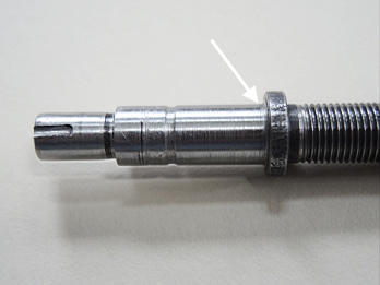
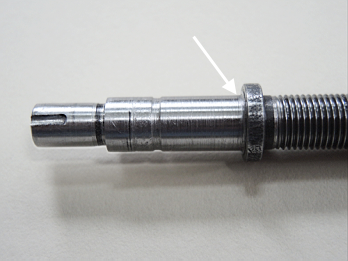
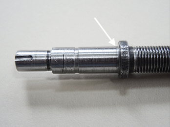
The outer end of the shaft is 12 mm. Turn the shaft to 10 mm to accept the 10 mm bore of the bearings.
Note: The inner race of the bearings is very thin, about 1 mm. Use a round nosed bit when turning down the shaft so that the transition where the shaft meets the outer edge of the flange is a slight ramp rather than perfectly square, or leave a small 1 mm ridge. The shaft should only contact the inner bearing race and not smash the entire side of the bearing flat against the side of the flange.
Step 3: Create a sleeve bushing for the dial
The dial has a bore of 12 mm, but the shaft is now 10 mm, so we need to create a sleeve bushing for the dial to fit the shaft.
Note: This is the step that completely removes the dial from participating in compressing the components between the flange and the bolt to remove runout.
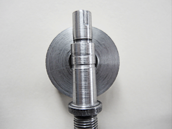
1. Face a short piece of ½” aluminum bar stock and turn a section about 10 mm longer than the dial is thick to 12 mm so that the dial slides smoothly on it without slop.
2. Drill the machined section of the aluminum bar to a 10 mm bore so the shaft fits into the bore smoothly without slop.
Note: One end of the sleeve you are creating will contact the outer bearing on the retainer. The bored section of the sleeve now has a wall thickness of 2 mm but the inner bearing race is 1 mm, so turn a very small section at the faced end of the sleeve down to 1 mm wall thickness to mate with the inner bearing race.
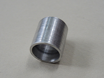
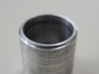
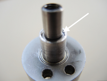
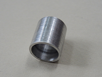
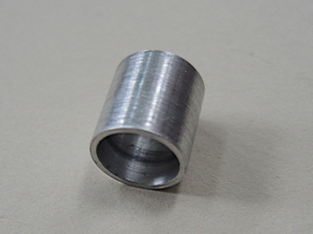
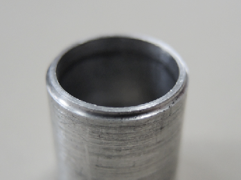
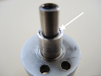
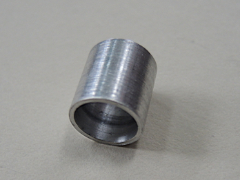
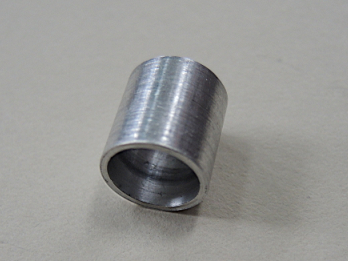
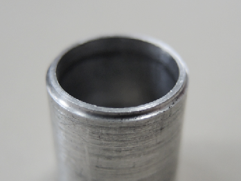
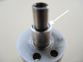
3. Cut off the bored, machined section of bar a little longer than the dial is thick to form the sleeve. The one pictured here is 13 mm in length. This is slightly longer than it needs to be, but it works well and is good for now. When the mod is complete and you understand how this fits, you may wish to shorten it slightly.
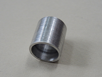
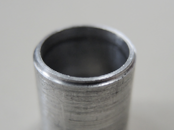
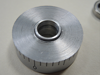
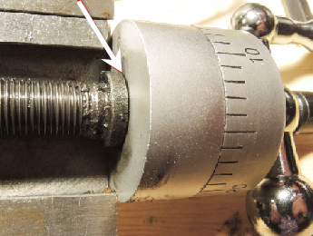
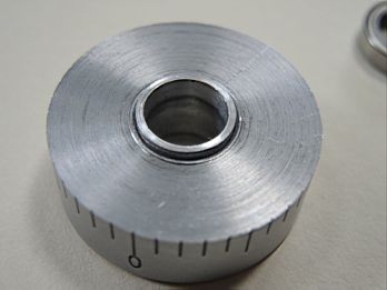
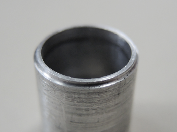
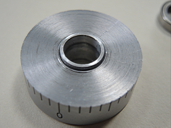
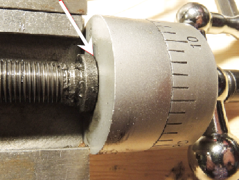
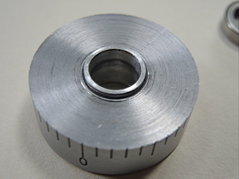
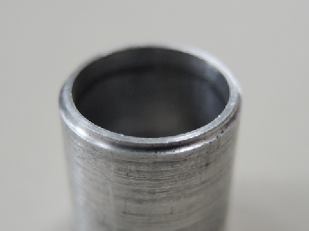
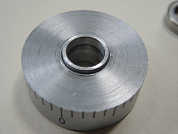
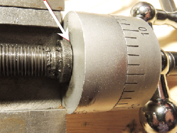
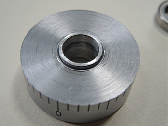
Pictured below is the sleeve in the dial. The sleeve must be slightly longer than the dial is thick so it extends proud of the dial. This is essential. Verify the sleeve is long enough so when it and the retainer are installed on the shaft the sleeve extends about 1 mm outward beyond the 10 mm section of the shaft, over the 8 mm shaft end that holds the handle.
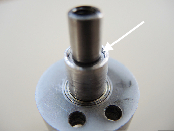
Step 4: Check out the progress!
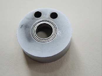
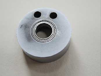
Place the bearings in the retainer and slide it on the shaft.
Place the sleeve on the shaft with the end machined to 1 mm wall thickness inward against the outer bearing in the retainer.
Place the spacer and handle onto the shaft. Insert the bolt and tighten to hand snug.
Grasp the retainer, spin the handle and enjoy! Smooth as silk with 100% zero runout.
Because the sleeve length extends beyond the 10 mm section of the shaft, when the bolt is tightened all runout is removed.
At this point the assembly is almost functionally complete and could be used; it just would not have the dial. Now you can understand how this mod completely removes the dial from needing to be compressed with the other components to remove runout. We are almost finished!
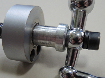
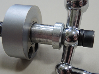
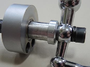
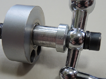
Remove the nut, handle and spacer and slide the dial over the sleeve onto the shaft. Replace the nut, handle and spacer. The dial should be free to rotate around the sleeve and slide along the shaft between the outer retainer surface and spacer.
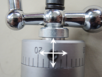
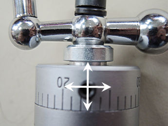
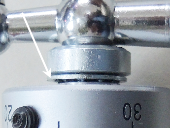
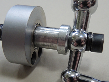
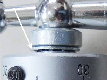
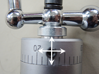
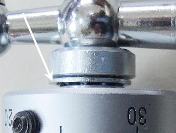
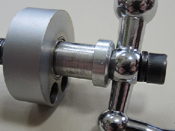
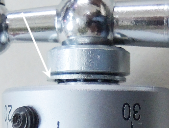
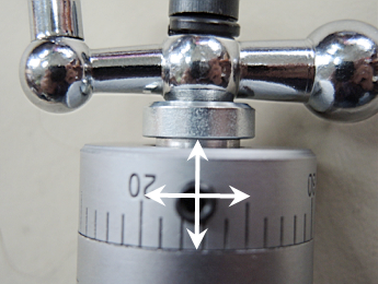
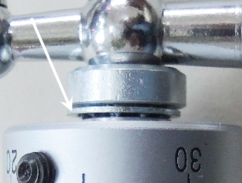
As mentioned at the start of Step 3, the sleeve is slightly longer than necessary, and accounts for the space between the dial and the spacer, (pictured below). The distance between the outer surface of the dial and the spacer may be reduced by slightly shortening the length of the sleeve. Be careful however. As previously mentioned, the sleeve must be long enough to extend beyond then 10 mm diameter section of the shaft, and there must be some play or the dial will bind and you will get to create a new sleeve. Also, discussed later, is the possibility of adding a very thin shim between the retainer and the dial. The shim is not necessary, but if you decide to shorten the sleeve and add a shim, the thickness of the shim would need to taken into consideration.
Step 5: Install a set screw in the dial
The dial now spins freely on the shaft, but enough rotational drag must be introduced so the dial will rotate with the shaft when the shaft is turned, but not so much drag as to preclude the dial from being manually rotated to zero out the graduation marks when the shaft is stationary.
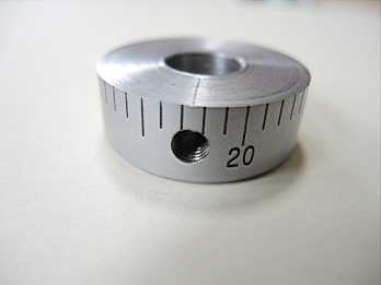
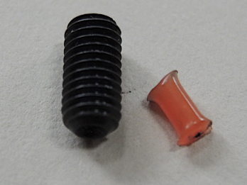
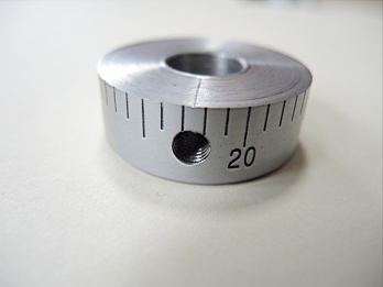
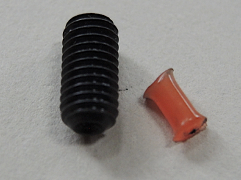
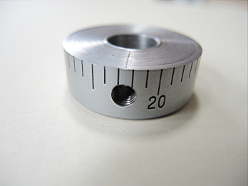
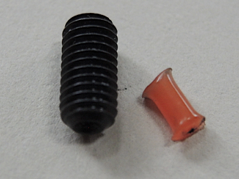
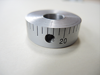
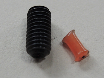
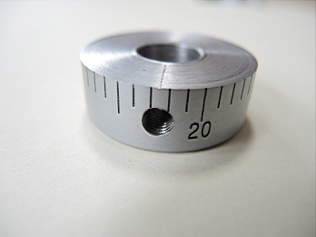
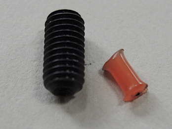
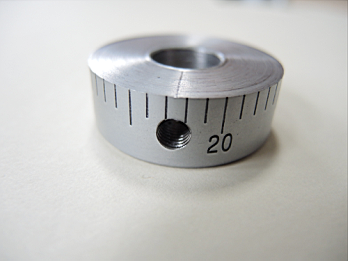
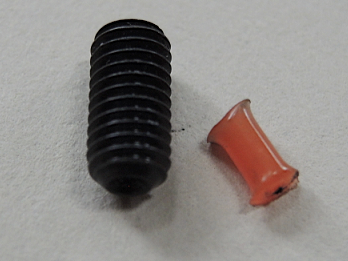
Drill a hole through one side of dial and tap it to accept a set screw. The set screw will not provide drag, but will instead compress a small piece of plastic between the set screw and the sleeve to achieve smooth, non damaging drag. I used a 5 mm set screw and a short piece of nylon grass trimmer line. The set screw shown below is too long and extends proud of the outer diameter of the dial, but it works and is what I had on hand.
Step 6: Install a keyway in the shaft and handle.
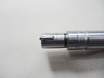
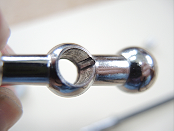
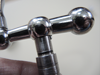
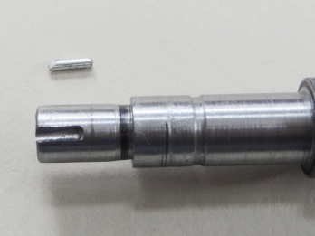
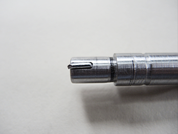
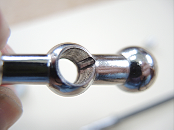
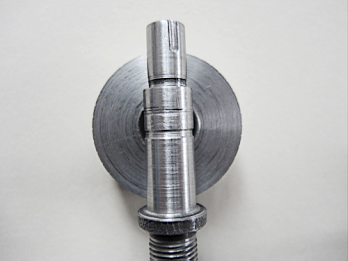
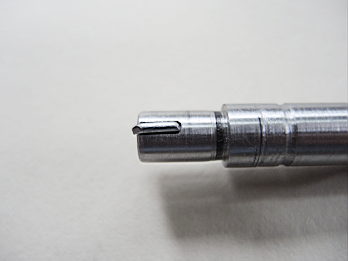
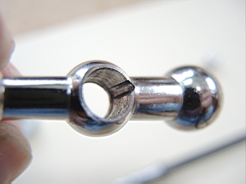
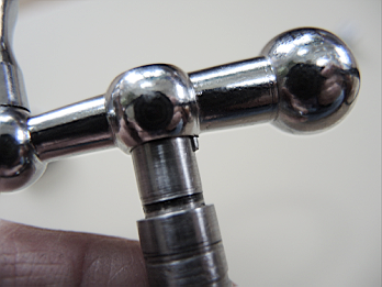
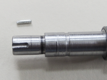
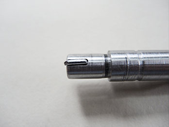
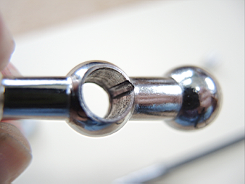
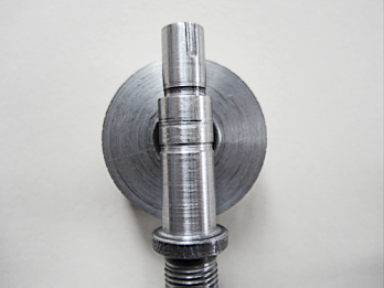
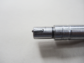
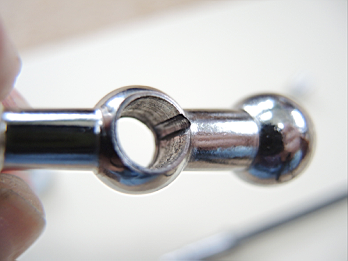
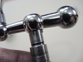
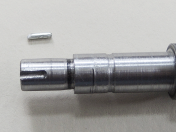
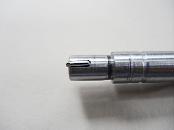
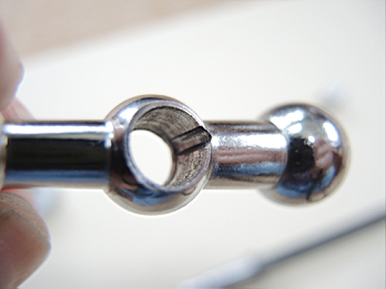
Because over tightening the bolt is not necessary, and is in fact detrimental in that it impedes rotational ease and can damage the bearings, it is possible that the handle can slip, and rotate on the shaft. To prevent this, install a keyway on the shaft and in the bore of the handle. The keyway should extend from the inside edge of the handle, but not all of the way through the outer edge of the handle. The handle will slide over the key and completely cover it.
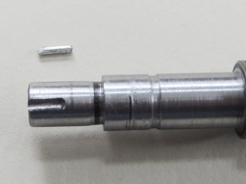
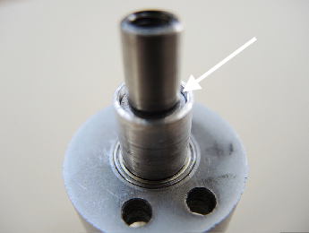
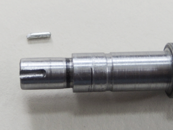
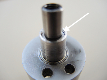
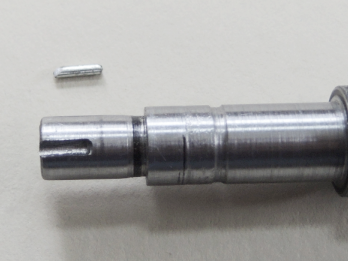
The keyway pictured below looks a little homely and homemade, because lacking a milling machine, I clamped the shaft in a vice and hand-held a rotary tool with a cylindrical diamond burr to create it. The little diamond burrs work well and are incredibly inexpensive. A 30 piece set is $6.89 at Amazon. Search for 82331TF.
Create a little key to fit the keyway. I cut a piece of paper clip for the key.
Step 7: Assembly - The Final Step!
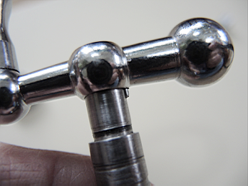
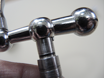
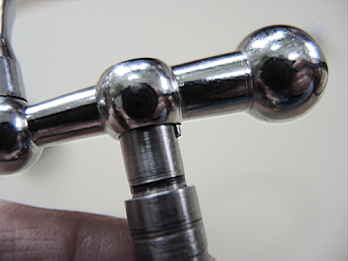
Note: Because over tightening the bolt is contraindicated, and the sleeve rotates with the shaft because it is held in place by pressure from the bolt squeezing the sleeve between the spacer and the outer retainer bearing, it is possible that the sleeve could slip when the shaft is rotated. This would result in the dial not moving with shaft rotation, and therefore, the shaft rotation would not be represented by corresponding movement of the dial.
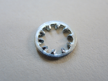
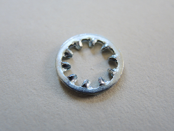
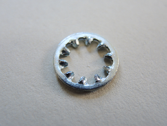
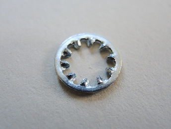
To prevent sleeve slippage, place the 8 mm or 5/16” internal tooth lock washer between the spacer and the sleeve during assembly.
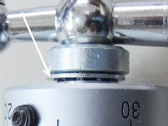
* Install the bearings in the retainer and place the retainer on the shaft.
* Place the sleeve on the shaft with the 1 mm wall thickness end of the sleeve against the outer bearing in the retainer.
* Slide the dial over the sleeve.
* Install the toothed lock washer, spacer, keyway key, handle and nut.
Note: Again – Do not over tighten the bolt. It only needs to be just snug. If you experiment with this you will find that if you tighten the bolt too much, rotational movement starts to feel restricted and the bearings do not rotate smoothly. I suspect this is due to the inner bearing race starting to deform under pressure. Not a good thing. So only snug the bolt as much as necessary.
Note: With the toothed washer installed, and a 13 mm long sleeve, the bolt is barely long enough grab the threads in the shaft. It works, but is iffy. To remedy this, install a longer bolt, or shorten the sleeve slightly, and/or install a thinner lock washer under the bolt, etc.
* Drop a little piece of plastic in the set screw hole and install the set screw. Tighten the set screw just enough so the dial rotates with shaft rotation, but not so much as to make manual rotation of the dial difficult while the shaft is held stationary. This provides extremely smooth, non-destructive drag for the dial.
Final note: While not necessary, a very thin shim may be installed between the dial and retainer to maintain an exact separation between the two. If you do this, make the spacer wall diameter, i.e., distance between ID and OD, as narrow as possible to avoid introducing any unnecessary drag in the system.
Congratulations! The mod is complete. Happy machining!
(C) Copyright 2016
I was motivated to design this mod because the compound slide on my machine suffered from runout originating in the screw assembly which I found unacceptable and unnecessary. Wear and/or poorly manufactured parts made it so tightening the bolt all the way did not resolve the issue. Adding shims to remove runout removed the runout, but the screw assembly became difficult to turn.
This mod works amazingly well. I can now adjust the compound slide by pressing a fingertip on the end of the handle, and there is no runout in the screw assembly.

This is a fairly extensive compound screw mod and requires a bit of machining fun. So why go to the trouble? Well, the factory issue doesn’t work very well do to poor design and it is manufactured to be inexpensive; lacking bearings or even sleeve bushings. The assembly is either prone to runout or binds and does not rotate smoothly and easily. There are multiple steps, but the mod is not difficult to do and the total cost is less than $10.00 US.
With this mod, 100% of runout is removed, and it rotates so smoothly it can actually be rotated with a feather. This is not an exaggeration. There is zero runout, and when the assembly is held by the retainer as pictured below, gently tapping the handle off its apogee causes the handle to continue to rotate most of the way to the bottom under its own weight.
That being said, there is another mod out there that utilizes one large bearing between the retainer and the dial, (reference below image), is considerably simpler to make and resolves 90% of the problems associated with the screw assembly. You may be completely satisfied with that mod. This mod adds two additional improvements by adding an additional bearing between the flange and the retainer, and it completely removes the dial as a component that must be compressed between the other components to remove runout.
To understand this unique mod, it is necessary to understand exactly how the screw assembly works, so please be patient with this introduction. Once understood, the design deficiencies and how to remedy them are apparent. For clarity, the following terms will be used consistently throughout these instructions.

Cause of runout or binding:
All the components are held between the bolt and flange. There is a small lip at the top of the outer edge of the bore in the handle, so the handle is not free to slide completely down the shaft. As the bolt is tightened, the other pieces slide down the shaft towards the flange until the outer end of the shaft reaches the lip at the outer edge in the handle bore. The bolt then simply tightens the handle to the shaft. With the handle secure to the shaft, the inner edge of the handle is a fixed distance from the flange. All of the components now must exist in this defined area between the flange and the inner edge of the handle.
Under ideal conditions, because the components are sized to fit in the defined area this sort of works, but not all that well, and is prone to failure. It fails when wear is introduced between the flange and the retainer, or the retainer and the dial, or the dial and the spacer. If any of these parts become worn, nonadjustable runout is introduced into the system because the components can slide on the shaft between the flange and the inner edge of the handle.
Inherent design flaws:
Because the shaft and all parts starting with the dial outward must be free to rotate, runout is in fact not only necessary but is designed in! There MUST be some slop so the components are free to move. If a shim is introduced between the flange and the retainer or the dial and the spacer, when bolt is tightened to remove all runout the mechanism locks up or binds, resulting in compromised ease of rotation.
Yet another design flaw is that in order to remove runout, the dial must press against the outer surface of the retainer, but the dial must be free to rotate separately from the shaft and the rest of the components so that it may be zeroed out. If the assembly is tightened enough to remove all runout, the inner dial surface binds against the outer surface of the retainer. Even if the two surfaces are lubricated it compromises ease of rotation.
This mod fully addresses the aforementioned problems.
Now, finally… On with the mod!
Parts and tools needed:
1. (2) 10 mm x 15 mm x 4 mm bearings. I picked up four from Amazon for $7.99 with free shipping. Enough for both the cross and compound slides.
2. (1) 5 mm set screw. $0.43
3. (1) 4” piece of ½” aluminum bar stock
4. 4.5 mm drill bit
5. 5 mm tap
6. 10 mm drill bit. I used a 25/64” (9.92 mm) bit. It was so close to 10 mm that a little sand paper finished the job.
7. 4 mm length nylon trimmer line or tiny chunk of plastic, Delrin , thermoplastic or the like. $0.00
8. Rotary tool with a burr bit or milling machine
9. Sturdy paper clip or a small finishing nail, etc.
10. (1) 8 mm or 5/16” internal tooth lock washer. Easily found at a hardware store for about $0.20.
Of course the SAE equivalently sized set screw, drill and tap could be substituted if that is what you have on hand.
Step 1: Install retainer bearings
Machine both sides of the retainer to accept the bearings to be flush with the retainer surface.


Step 2: Reduce shaft diameter
The outer end of the shaft is 12 mm. Turn the shaft to 10 mm to accept the 10 mm bore of the bearings.
Note: The inner race of the bearings is very thin, about 1 mm. Use a round nosed bit when turning down the shaft so that the transition where the shaft meets the outer edge of the flange is a slight ramp rather than perfectly square, or leave a small 1 mm ridge. The shaft should only contact the inner bearing race and not smash the entire side of the bearing flat against the side of the flange.

Step 3: Create a sleeve bushing for the dial
The dial has a bore of 12 mm, but the shaft is now 10 mm, so we need to create a sleeve bushing for the dial to fit the shaft.
Note: This is the step that completely removes the dial from participating in compressing the components between the flange and the bolt to remove runout.

1. Face a short piece of ½” aluminum bar stock and turn a section about 10 mm longer than the dial is thick to 12 mm so that the dial slides smoothly on it without slop.
2. Drill the machined section of the aluminum bar to a 10 mm bore so the shaft fits into the bore smoothly without slop.
Note: One end of the sleeve you are creating will contact the outer bearing on the retainer. The bored section of the sleeve now has a wall thickness of 2 mm but the inner bearing race is 1 mm, so turn a very small section at the faced end of the sleeve down to 1 mm wall thickness to mate with the inner bearing race.
3. Cut off the bored, machined section of bar a little longer than the dial is thick to form the sleeve. The one pictured here is 13 mm in length. This is slightly longer than it needs to be, but it works well and is good for now. When the mod is complete and you understand how this fits, you may wish to shorten it slightly.


Pictured below is the sleeve in the dial. The sleeve must be slightly longer than the dial is thick so it extends proud of the dial. This is essential. Verify the sleeve is long enough so when it and the retainer are installed on the shaft the sleeve extends about 1 mm outward beyond the 10 mm section of the shaft, over the 8 mm shaft end that holds the handle.


Step 4: Check out the progress!
Place the bearings in the retainer and slide it on the shaft.
Place the sleeve on the shaft with the end machined to 1 mm wall thickness inward against the outer bearing in the retainer.
Place the spacer and handle onto the shaft. Insert the bolt and tighten to hand snug.
Grasp the retainer, spin the handle and enjoy! Smooth as silk with 100% zero runout.
Because the sleeve length extends beyond the 10 mm section of the shaft, when the bolt is tightened all runout is removed.
At this point the assembly is almost functionally complete and could be used; it just would not have the dial. Now you can understand how this mod completely removes the dial from needing to be compressed with the other components to remove runout. We are almost finished!

Remove the nut, handle and spacer and slide the dial over the sleeve onto the shaft. Replace the nut, handle and spacer. The dial should be free to rotate around the sleeve and slide along the shaft between the outer retainer surface and spacer.
As mentioned at the start of Step 3, the sleeve is slightly longer than necessary, and accounts for the space between the dial and the spacer, (pictured below). The distance between the outer surface of the dial and the spacer may be reduced by slightly shortening the length of the sleeve. Be careful however. As previously mentioned, the sleeve must be long enough to extend beyond then 10 mm diameter section of the shaft, and there must be some play or the dial will bind and you will get to create a new sleeve. Also, discussed later, is the possibility of adding a very thin shim between the retainer and the dial. The shim is not necessary, but if you decide to shorten the sleeve and add a shim, the thickness of the shim would need to taken into consideration.

Step 5: Install a set screw in the dial
The dial now spins freely on the shaft, but enough rotational drag must be introduced so the dial will rotate with the shaft when the shaft is turned, but not so much drag as to preclude the dial from being manually rotated to zero out the graduation marks when the shaft is stationary.
Drill a hole through one side of dial and tap it to accept a set screw. The set screw will not provide drag, but will instead compress a small piece of plastic between the set screw and the sleeve to achieve smooth, non damaging drag. I used a 5 mm set screw and a short piece of nylon grass trimmer line. The set screw shown below is too long and extends proud of the outer diameter of the dial, but it works and is what I had on hand.


Step 6: Install a keyway in the shaft and handle.
Because over tightening the bolt is not necessary, and is in fact detrimental in that it impedes rotational ease and can damage the bearings, it is possible that the handle can slip, and rotate on the shaft. To prevent this, install a keyway on the shaft and in the bore of the handle. The keyway should extend from the inside edge of the handle, but not all of the way through the outer edge of the handle. The handle will slide over the key and completely cover it.
The keyway pictured below looks a little homely and homemade, because lacking a milling machine, I clamped the shaft in a vice and hand-held a rotary tool with a cylindrical diamond burr to create it. The little diamond burrs work well and are incredibly inexpensive. A 30 piece set is $6.89 at Amazon. Search for 82331TF.
Create a little key to fit the keyway. I cut a piece of paper clip for the key.


Step 7: Assembly - The Final Step!
Note: Because over tightening the bolt is contraindicated, and the sleeve rotates with the shaft because it is held in place by pressure from the bolt squeezing the sleeve between the spacer and the outer retainer bearing, it is possible that the sleeve could slip when the shaft is rotated. This would result in the dial not moving with shaft rotation, and therefore, the shaft rotation would not be represented by corresponding movement of the dial.
To prevent sleeve slippage, place the 8 mm or 5/16” internal tooth lock washer between the spacer and the sleeve during assembly.


* Install the bearings in the retainer and place the retainer on the shaft.
* Place the sleeve on the shaft with the 1 mm wall thickness end of the sleeve against the outer bearing in the retainer.
* Slide the dial over the sleeve.
* Install the toothed lock washer, spacer, keyway key, handle and nut.
Note: Again – Do not over tighten the bolt. It only needs to be just snug. If you experiment with this you will find that if you tighten the bolt too much, rotational movement starts to feel restricted and the bearings do not rotate smoothly. I suspect this is due to the inner bearing race starting to deform under pressure. Not a good thing. So only snug the bolt as much as necessary.
Note: With the toothed washer installed, and a 13 mm long sleeve, the bolt is barely long enough grab the threads in the shaft. It works, but is iffy. To remedy this, install a longer bolt, or shorten the sleeve slightly, and/or install a thinner lock washer under the bolt, etc.
* Drop a little piece of plastic in the set screw hole and install the set screw. Tighten the set screw just enough so the dial rotates with shaft rotation, but not so much as to make manual rotation of the dial difficult while the shaft is held stationary. This provides extremely smooth, non-destructive drag for the dial.
Final note: While not necessary, a very thin shim may be installed between the dial and retainer to maintain an exact separation between the two. If you do this, make the spacer wall diameter, i.e., distance between ID and OD, as narrow as possible to avoid introducing any unnecessary drag in the system.
Congratulations! The mod is complete. Happy machining!


Last edited:

