Mill tramming question (non axis tramming?)

jeremysf

Registered
Registered
Joined
Mar 2, 2021
Messages
84
Hi,

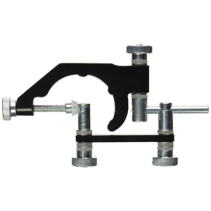
I am attempting to tram a bridgeport style turret/knee mill with a tramming square (i.e. two DTI mounted on arms and held in the quill).

I can get the within a thou on both the x-axis and the y-axis.

If I then rotate the quill a few degrees off axis (or say to 45 degrees) the DTIs are way off from each other (like maybe tens of thous?).

When the quill rotates through 90 degrees (i.e. axis aligned on the x-axis or y-axis) the DTI's agree.

Does that seem weird? Wouldn't that mean that something like a fly cutter would cut "waves" rather than a flat circle?

What am I missing?

Thanks for reading!
 
Did you stone with ground tool room stones and then clean the table?
 
Rotate quill???

The part of the quill that extends does not rotate.

You extend the quill fully and use the side as it is a straight surface that you can reference to in 2 places, top and bottom to check for angle.

You check front and side.

You also should push it towards your DI to see if it moves.


Sent from my SM-G781V using Tapatalk
 
Try sweeping an indicator. I suspect you are using the dual indicators incorrectly in some way. It’s pretty hard to be confused by a single indicator.
 
Sorry, some more details:

It’s a brand new PM-1054TV mill, so I don’t think the bed is to blame.

When I said “rotate the quill”, I meant, I put the motor gearing in neural and was rotating the spindle. The tramming square is secured tightly in an R8 collet.

The two DTI agree when rotated 180 degrees (rotated either on the x axis, or the y axis).

I will try the suggestion of sweeping a single test indicator in a collet instead.of a DTI in the tramming square. Smaller radius but less variables.

In that setup, with a theoretical perfectly trammed head, and theoretical perfect runout spindle and theoretical perfectly flat bed, the indicator should read the same as it is swept right?

In the real world, on a brand new good quality machine, it should be possible for the swept indicator to vary by less than a thou or three right?

Thanks!
 
Yes, when sweeping with an indicator on a good table surface, it should be zero all the way around the circle. Variations suggest a problem with the spindle bearings or the table.
 
Yes, when sweeping with an indicator on a good table surface, it should be zero all the way around the circle. Variations suggest a problem with the spindle bearings or the table.

Thank you! This is the answer I was looking for. In this case, operator error was the cause. Unclear what I was doing wrong initially but sorted now:

https://youtu.be/fIbMpILDxBo

I would be so lost without this forum and its awesome users!
 
Thank you! This is the answer I was looking for. In this case, operator error was the cause. Unclear what I was doing wrong initially but sorted now:


I would be so lost without this forum and its awesome users!
Assuming that is your video, tramming to the top of the vise is not recommended, there are just too many potential variables. Always tram to the table, the larger diameter sweep the better. I use an Indicol style holder because it will adjust to sweep the entire width of the table and is so versatile for indicating the vise, holes and other setups without having to remove what is in the spindle.

1630000718567.png
 
Back
Top