- Joined
- Mar 26, 2018
- Messages
- 2,725
Hi All,
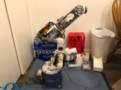
I'm very excited to share that after nearly 5 years of searching high and low, I have finally found a 6 axis robot that was affordable enough and the right size/shape for me to justify purchasing.
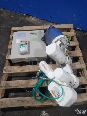
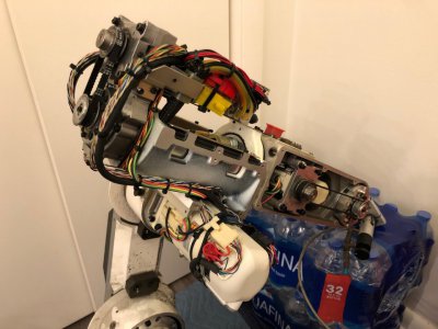
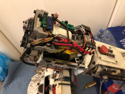
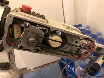
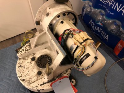
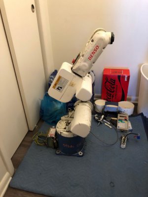
This robot is a 1999 Denso VS-6354CM 6 axis vertically articulated robot. These are the most flexible of all the robot types and can move around in 3D space, plus position the tool in any orientation (given that the workspace constraints allow it). This unit would typically be used for high speed, high accuracy, low payload applications. The previous owner had a air actuated dispensing tool on the end of the arm for spraying some sort of dark grey enamel or paint. There is a fair bit of overspray on the robot which I hope to find a solvent to remove, otherwise both the robot and controller are remarkably clean.
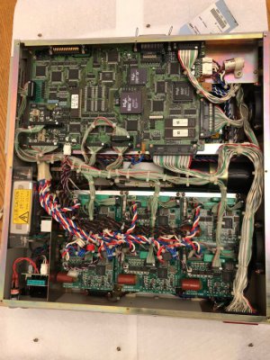
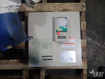
This was purchased from HGR.com, an industrial surplus supplier in Cleveland for less than $400. New robots of this size can run from $20k and up depending on options and software. I have never seen one sell this inexpensively so I had to jump on it. I plan to do a lot of research into this unit and hopefully get it running again. The robot did come with a matching controller and a teach pendant, however these are only 2 parts of the system needed to run the robot as the manufacturer intended. Many are currently available on eBay, however they total to more than the cost of the robot.
I plan to keep this thread formatted much like the project log for the other robot I own, a 4 axis SCARA robot. If you haven't seen that thread, check it out here: https://www.hobby-machinist.com/threads/mikes-scara-robot.84001/
General:
Motors:
Again, not much of a machining project, but I enjoy this community and hope you will follow along!
-Mike
I think this is the last robot my wife will let me bring home
EDIT 1/31/2022: Added data from manuals. Added some motor data.
EDIT 2/3/2022: Added missing motor part numbers. Added some motor data.
EDIT 2/8/2022: Added info about replacement J6 motor and mechanics information on J4, J5, J6.
EDIT 2/10/2022: Added mechanics information on J1, J2, J3
EDIT 2/14/2022: Corrected gearbox ratio
EDIT 3/3/2022: Confirmed J3 gear ratio, added J3 gearbox part number
I'm very excited to share that after nearly 5 years of searching high and low, I have finally found a 6 axis robot that was affordable enough and the right size/shape for me to justify purchasing.

This robot is a 1999 Denso VS-6354CM 6 axis vertically articulated robot. These are the most flexible of all the robot types and can move around in 3D space, plus position the tool in any orientation (given that the workspace constraints allow it). This unit would typically be used for high speed, high accuracy, low payload applications. The previous owner had a air actuated dispensing tool on the end of the arm for spraying some sort of dark grey enamel or paint. There is a fair bit of overspray on the robot which I hope to find a solvent to remove, otherwise both the robot and controller are remarkably clean.
This was purchased from HGR.com, an industrial surplus supplier in Cleveland for less than $400. New robots of this size can run from $20k and up depending on options and software. I have never seen one sell this inexpensively so I had to jump on it. I plan to do a lot of research into this unit and hopefully get it running again. The robot did come with a matching controller and a teach pendant, however these are only 2 parts of the system needed to run the robot as the manufacturer intended. Many are currently available on eBay, however they total to more than the cost of the robot.
I plan to keep this thread formatted much like the project log for the other robot I own, a 4 axis SCARA robot. If you haven't seen that thread, check it out here: https://www.hobby-machinist.com/threads/mikes-scara-robot.84001/
General:
- Manufacturer: Denso Robotics (Headquartered in Japan)
- Model: VS-6354CM
- Software Version: 9.57
- Date Mfg.: December 6,1999
- No. of Axes/Degrees Of Freedom: 6
- Weight: 28kg (62lbs)
- Payload: Up to 5kg (11lbs) with reduced dynamics. Rated dynamics at 1kg.
- Operation Station:
- Teach Pendant Cable:
- Robot Motor Cable:
- Robot Encoder Cable:
- Controller Power Cable:
- IO Output 1 Cable:
- IO Output 2 Cable:
- IO Input Cable:
- IO Valve Cable:
- Floppy Drive:
- Floppy Drive Cable:
- Calibration Data File (Floppy Disk):
- WinCAPS Robot File (Floppy Disk):
- Parameter File (Floppy Disk):
- Base/J1 Offset: (100mm, 0mm, 335mm)
- J2/J3 Link Length: 255mm
- J3/Wrist Center "P" Length: 285mm
- Wrist Center "P"/Tool Flange Face: R75mm
- Spherical Wrist
- Positioning Repeatability: +/-0.0008" or +/-0.02mm
- Positioning Accuracy: Not stated - determined by calibration, movement accuracy, joint length accuracy, etc. Usually within 0.005"
- Max Reach at wrist center from center of base: 25.66" (652mm)
- Min Reach at wrist center from center of base: 10.43" (265mm)
- J1 Range: +/- 140 degrees (nominal)
- J2 Range: +100/-55 degrees (nominal)
- J3 Range: +73/-103 degrees (nominal) - this needs a double check
- J4 Range: +/- 168 degrees (nominal)
- J5 Range: +/- 120 degrees (nominal)
- J6 Range: Continuous Rotary
- J1/J2 Max Angular Speed (1kg payload): 176 degrees/s - Note 1
- J3/J4/J5 Max Angular Speed (1kg pyload): 209 degrees/s - Note 1
- J6 Max Angular Speed (1kg payload): 290 degrees/s - Note 1
- XY Max Cartesian Speed (1kg payload): 857mm/s or 2024 inch/min or 1.9 mph - Note 1
- J1 Calibration Position: 142.867
- J2 Calibration Position: -57.6772
- J3 Calibration Position: 164.806
- J4 Calibration Position: 171.339
- J5 Calibration Position: 126.247
- J6 Calibration Position: 92.0430
Motors:
- Motor Type: Panasonic Minas-A Series (I think). Licensed to DENSO with DENSO-only part numbers. Panasonic Part Numbers in bold.
- Encoder Type: Tamagawa TS5643N151 98 17-bit absolute multiturn battery-backed serial encoders. This may differ between motors.
- --------------------
- J1 Part #: 410622-0491 (S/N: 11U15) MSM022Q6U
- J1 Encoder Part #: ?
- --------------------
- J2 Part #: 410622-0501 (S/N: 11U15) MSM042Q6V (Motor has 24VDC electromagnetic holding brake)
- J2 Encoder Part #: ?
- --------------------
- J3 Part #: 410622-0511 (S/N: 11U16) MSM022Q6V (Motor has 24VDC electromagnetic holding brake)
- J3 Encoder Part #: ?
- --------------------
- J4 Part #: 410622-0551 (S/N: 11U16) MSM5AZQ6Q
- J4 Encoder Part #: TS5643N151
- --------------------
- J5 Part #: 410622-0561 (S/N: 11U16) MSM5AZQ6Q
- J5 Encoder Part #: TS5643N151
- --------------------
- J6 Part #: 410622-0571 (S/N: 11U16) MSM5AZQ6Q
- Replacement J6 Part #: 410622-0631 (S/N: 01I10) MSM5AZQ6Q
- J6 Encoder Part #: TS5643N151 98 (S/N: B32803E)
- J1 Gearing arrangement: Direct Drive to Harmonic Gearset
- J1 Harmonic Gearset Ratio/Part #: 100:1 (calculated), P/N unknown
- --------------------
- J2 Gearing arrangement: Direct Drive to Harmonic Gearset
- J2 Harmonic Gearset Ratio/Part #: 100:1, Harmonic Drive P/N: 25-100-921494-17
- --------------------
- J3 Gearing arrangement: Direct Drive to Harmonic Gearset
- J3 Harmonic Gearset Ratio/Part #: 80:1, Harmonic Drive P/N: 20-80-921496-12
- --------------------
- J4 Gearing arrangement: Belt Drive to Harmonic Gearset
- J4 Belt Ratio/Tooth Count/Part #: 1:1, 28T (driving) to 28T (driven), Belt: MBL S3M219
- J4 Harmonic Gearset Ratio/Part #: 80:1, Harmonic Drive P/N: HS14-80-921773-14
- J4 Total Gear Ratio: 80:1
- --------------------
- J5 Gearing arrangement: Belt Drive to Harmonic Gearset
- J5 Belt Ratio/Tooth Count/Part #: 1:1, 28T (driving) to 28T (driven), Belt: ???
- J5 Harmonic Gearset Ratio/Part #: 80:1, Harmonic Drive P/N: HS14-80-921773-5
- J5 Total Gear Ratio: 80:1
- --------------------
- J6 Gearing arrangement: Belt Drive to Bevel gearset to Harmonic Gearset
- J6 Belt Ratio/Tooth Count/Part #: Ratio: 1:1, 28T (driving) to 28T (driven), Belt: MBL S3M267
- J6 Bevel Gearset Ratio/Tooth Count: Ratio: 1:1, 20T (driving) to 20T (driven)
- J6 Harmonic Gearset Ratio/Part #: Ratio: 50:1, Harmonic Drive P/N: SF14-50-921826-4
- J6 Total Pre-J5 Coupling Ratio: 1:1
- J6 Total Post-J5 Coupling Ratio: 50:1
- Torque mounting bolts and gearbox bolts to spec (in Chapter 6 of manual) every 3 months (~250-500 hours of operation)
- Clean controller fan filters every 3 months (~250-500 hours of operation)
- Drain grease and pump new grease into each joint every 4000 hours of operation (1-2 years depending on duty cycle).
- Apply grease to inside of plastic covers where wire bundles slide every 4000 hours of operation (1-2 years depending on duty cycle).
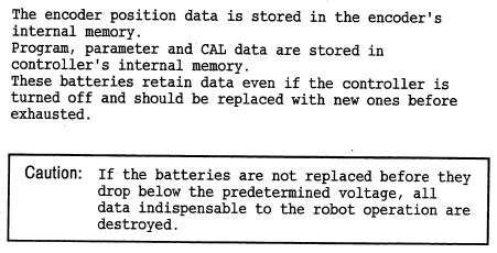
- Replace encoder backup battery every 2 years.
- Replace controller memory backup battery every 2 years.
- Grease: Kyodo Yushi, MULTEMP AC-N high performance lithium grease made from synthetic hydrocarbon oil and synthetic ester oil.
- 10 conductors for robot tool passthrough. Available on back of wrist.
- 1 air/process gas inlet. Internal solenoid valves. (3) double acting valves. (6) output ports available on back of wrist.
- CN10 (Control Motor Power): JAE 24-28S
- CN11 (Control Power Input): DDK 18-10 CE05 JAPAN
- CN13 (Robot Motor Power): JAE 24-B28PC
- CN20 (Robot Tool Input): JAE 25-24PC
- Rated Power (W): 200
- Torque Constant (N*m/A_rms): ???
- Rated Torque (N*m): ???
- Peak Torque (N*m): ???
- Inertia (Kg*m^2): ???
- Poles Per Revolution (n): ???
- Winding Resistance (Ohms): ???
- Winding Inductance (H): ???
- Inductive Time Constant (ms): ???
- Rated Voltage (Volts): 200
- Rated Speed (RPM): 3000
- Maximum Speed (RPM): 5000
- Continuous Current (A): ???
- Peak Current (A): ???
- Damping Coefficient (N*m/(Rad/s)): ???
- Voltage Constant (V_rms/k_RPM): ???
- Overload Limit (%): ???
- Acceleration (Rev/s^2): ???
- Thermal Model Parameters:
- Rth-we (C/W): ???
- Cth-we (W*s/C): ???
- Rth-wa (C/W): ???
- Cth-wa (W*s/C): ???
- Flux Saturation Curve (% Nominal Inductance): Use 1.0 for all values
- Brake: None
- Rated Power (W): 400
- Torque Constant (N*m/A_rms): ???
- Rated Torque (N*m): ???
- Peak Torque (N*m): ???
- Inertia (Kg*m^2): ???
- Poles Per Revolution (n): ???
- Winding Resistance (Ohms): ???
- Winding Inductance (H): ???
- Inductive Time Constant (ms): ???
- Rated Voltage (Volts): 200
- Rated Speed (RPM): 3000
- Maximum Speed (RPM): 5000
- Continuous Current (A): ???
- Peak Current (A): ???
- Damping Coefficient (N*m/(Rad/s)): ???
- Voltage Constant (V_rms/k_RPM): ???
- Overload Limit (%): ???
- Acceleration (Rev/s^2): ???
- Thermal Model Parameters:
- Rth-we (C/W): ???
- Cth-we (W*s/C): ???
- Rth-wa (C/W): ???
- Cth-wa (W*s/C): ???
- Flux Saturation Curve (% Nominal Inductance): Use 1.0 for all values
- Brake: 24VDC, power to release
- Rated Power (W): 200
- Torque Constant (N*m/A_rms): ???
- Rated Torque (N*m): ???
- Peak Torque (N*m): ???
- Inertia (Kg*m^2): ???
- Poles Per Revolution (n): ???
- Winding Resistance (Ohms): ???
- Winding Inductance (H): ???
- Inductive Time Constant (ms): ???
- Rated Voltage (Volts): 200
- Rated Speed (RPM): 3000
- Maximum Speed (RPM): 5000
- Continuous Current (A): ???
- Peak Current (A): ???
- Damping Coefficient (N*m/(Rad/s)): ???
- Voltage Constant (V_rms/k_RPM): ???
- Overload Limit (%): ???
- Acceleration (Rev/s^2): ???
- Thermal Model Parameters:
- Rth-we (C/W): ???
- Cth-we (W*s/C): ???
- Rth-wa (C/W): ???
- Cth-wa (W*s/C): ???
- Flux Saturation Curve (% Nominal Inductance): Use 1.0 for all values
- Brake: 24VDC, power to release
- Rated Power (W): 50
- Torque Constant (N*m/A_rms): ???
- Rated Torque (N*m): ???
- Peak Torque (N*m): ???
- Inertia (Kg*m^2): ???
- Poles Per Revolution (n): ???
- Winding Resistance (Ohms): ???
- Winding Inductance (H): ???
- Inductive Time Constant (ms): ???
- Rated Voltage (Volts): 100/200
- Rated Speed (RPM): 3000
- Maximum Speed (RPM): 5000
- Continuous Current (A): ???
- Peak Current (A): ???
- Damping Coefficient (N*m/(Rad/s)): ???
- Voltage Constant (V_rms/k_RPM): ???
- Overload Limit (%): ???
- Acceleration (Rev/s^2): ???
- Thermal Model Parameters:
- Rth-we (C/W): ???
- Cth-we (W*s/C): ???
- Rth-wa (C/W): ???
- Cth-wa (W*s/C): ???
- Flux Saturation Curve (% Nominal Inductance): Use 1.0 for all values
- Brake: None


Again, not much of a machining project, but I enjoy this community and hope you will follow along!
-Mike
I think this is the last robot my wife will let me bring home
EDIT 1/31/2022: Added data from manuals. Added some motor data.
EDIT 2/3/2022: Added missing motor part numbers. Added some motor data.
EDIT 2/8/2022: Added info about replacement J6 motor and mechanics information on J4, J5, J6.
EDIT 2/10/2022: Added mechanics information on J1, J2, J3
EDIT 2/14/2022: Corrected gearbox ratio
EDIT 3/3/2022: Confirmed J3 gear ratio, added J3 gearbox part number
Last edited:

