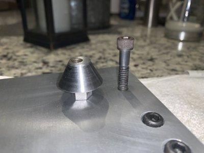
For Christmas, my wonderful bride gave me the MLA-13 ball turning / boring attachment kit. Don't know if I will ever use the boring attachment, but liked the ball turner design. Thought I would share my build experience for anyone interested.
The kit comes well documented and Andrew is very supportive, responding to email questions within 24 hours (only question I had was what type of lubricant to apply to the bearing).
The challenge was throwing the majority of the dimensions out the window since the unit was designed for a 9-12" lathe and mine is a 16". That required some additional thinking juice so the first thing I made for this project was a juice dispenser:

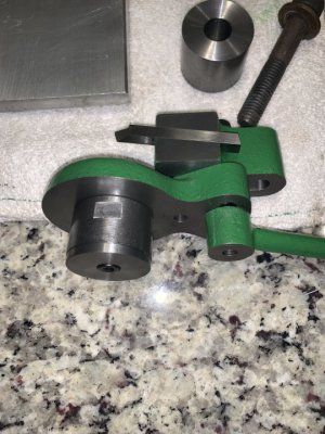
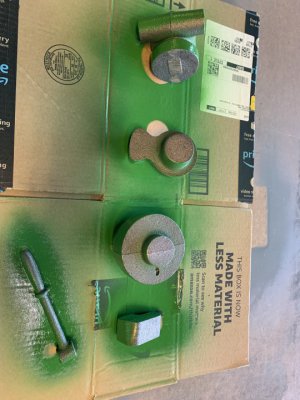
Following Andrews lead, I de-burred everything and painted it all with Rust-O implement paint (shown half painted so you can see the raw castings):
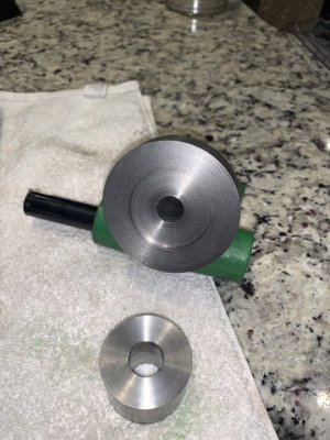
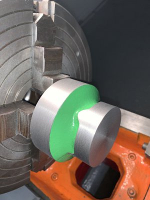
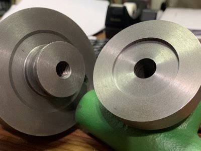
Started turning down all the OD's and ID's per the provided drawings. I left all the material I could in hopes of reaching spindle center on my 16":
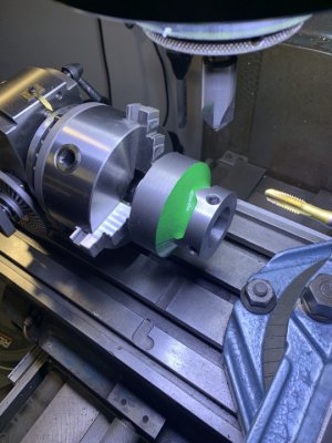
After the above, I was pretty much on my own. Started by making an adapter plate utilizing my cross slides dove tails and compound mounting screws:
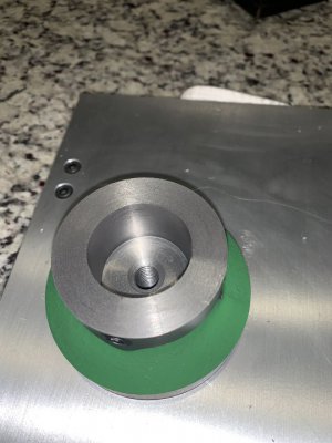
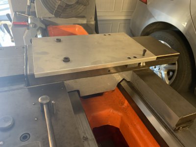 The screw sticking up on the far side is mounted eccentric, drawing the adapter plate up tight before tightening the dovetail clamps. The big screws are the compound mounting screws, we tighten those last. The plate is rock solid and very snug when tightened up. What is not shown in the picture is I ultimately recessed the ball turner in the plate, sinking the ball turner in about .250. This put the attachment on center line with the spindle.
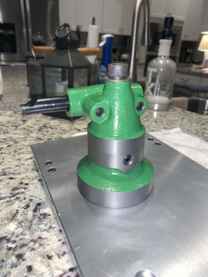
The unit turned out very good. I kept very tight tolerances between the metal bearing and the turning post which resulted in very smooth pivoting. I intentionally took the depth of the bearing a little deeper so that I could add and remove shim stock to get the resistance I wanted. Currently, I have a .002 shim and two .001 shims installed and the pivot is smooth as silk with just enough resistance. As the unit wears, I can remove a shim and tighten it back up.
I finished later on Sunday than I had planned but couldn't walk away without at least trying it out once. Here is the turner mounted on the plate and a ball turned out of some scrap steel I had. No, not scrap, just yet to be used. Stuff is too expensive these days for any of it to be called scrap.
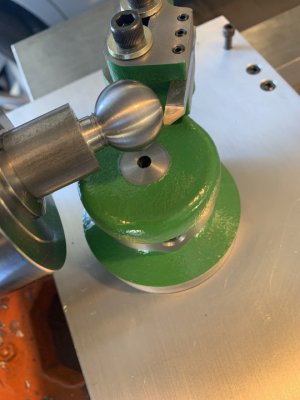 I was in a hurry when I did this. It's 1" diameter, turned at 700 rpm using an HSS cutter that I quickly ground. Finish on the ball was great, no chatter and great looking, smooth chips coming off.
A few seconds with some 400 sand paper (all I had) and some Flitz and here it is.
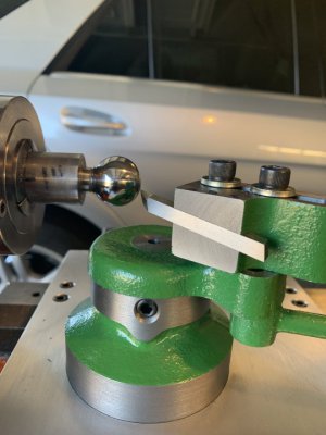
I still have to figure out how to properly set it up to hit specific dimensions, but I like the design. I missed something as I was trying to figure proper height. When properly set up, the ball turning attachment sits .110 lower than the boring bar on my set up. I don't plan on using the boring bar set up but provisioned for it just the same. I added a .110 spacer to the recess in the plate to accommodate for the difference. Again, this is on my set up and not a reflection on the kit. I tried to keep the two set ups in mind when machining, but I missed something somewhere, I don't know where. Only limitation I see is it looks like it maxes out at about 1" radius, 2" diameters. Overall tho, I like it.
The kit comes well documented and Andrew is very supportive, responding to email questions within 24 hours (only question I had was what type of lubricant to apply to the bearing).
The challenge was throwing the majority of the dimensions out the window since the unit was designed for a 9-12" lathe and mine is a 16". That required some additional thinking juice so the first thing I made for this project was a juice dispenser:

Following Andrews lead, I de-burred everything and painted it all with Rust-O implement paint (shown half painted so you can see the raw castings):

Started turning down all the OD's and ID's per the provided drawings. I left all the material I could in hopes of reaching spindle center on my 16":


After the above, I was pretty much on my own. Started by making an adapter plate utilizing my cross slides dove tails and compound mounting screws:
 The screw sticking up on the far side is mounted eccentric, drawing the adapter plate up tight before tightening the dovetail clamps. The big screws are the compound mounting screws, we tighten those last. The plate is rock solid and very snug when tightened up. What is not shown in the picture is I ultimately recessed the ball turner in the plate, sinking the ball turner in about .250. This put the attachment on center line with the spindle.
The unit turned out very good. I kept very tight tolerances between the metal bearing and the turning post which resulted in very smooth pivoting. I intentionally took the depth of the bearing a little deeper so that I could add and remove shim stock to get the resistance I wanted. Currently, I have a .002 shim and two .001 shims installed and the pivot is smooth as silk with just enough resistance. As the unit wears, I can remove a shim and tighten it back up.
I finished later on Sunday than I had planned but couldn't walk away without at least trying it out once. Here is the turner mounted on the plate and a ball turned out of some scrap steel I had. No, not scrap, just yet to be used. Stuff is too expensive these days for any of it to be called scrap.
 I was in a hurry when I did this. It's 1" diameter, turned at 700 rpm using an HSS cutter that I quickly ground. Finish on the ball was great, no chatter and great looking, smooth chips coming off.
A few seconds with some 400 sand paper (all I had) and some Flitz and here it is.

I still have to figure out how to properly set it up to hit specific dimensions, but I like the design. I missed something as I was trying to figure proper height. When properly set up, the ball turning attachment sits .110 lower than the boring bar on my set up. I don't plan on using the boring bar set up but provisioned for it just the same. I added a .110 spacer to the recess in the plate to accommodate for the difference. Again, this is on my set up and not a reflection on the kit. I tried to keep the two set ups in mind when machining, but I missed something somewhere, I don't know where. Only limitation I see is it looks like it maxes out at about 1" radius, 2" diameters. Overall tho, I like it.

