Measuring precision length while part is on the lathe

John TV

Registered
Registered
Joined
Mar 15, 2016
Messages
247
Very new, just a handful of hours on my Logan 10 inch lathe. No dro and so far just doing non critical parts with huge tolerance forgiveness. But I started thinking about different ways to precisely measure and mark work for length while it is in the lathe. So far just using sharpie and scratch method using cutting tool or calipers. what if you really need something within a few thou, what are people doing for layout? I can't say I have a good memory but I don't remember seeing this on YouTube. If someone can point me to written or video info that would be great.


Sent from my iPhone using Tapatalk
 
One method would be to mount an indicator to the bed or ways (by clamp or magnet) and have it bear against the carriage to measure movement.
 
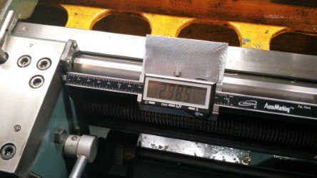
20170713_172909.jpg Might want to check into a magnet mount or even hard mounted and movable 3-4 in dial indicator preloaded against the carriage or plate attached to the carriage. I put a mag back on a 3 " dial indicator. I just up graded to the igageing type scales and added a blue tooth touch dro to read out to my tablet. See Randy Richards youtube video. I consider myself a newbe hobbiest.
 
Last edited:
It depends upon what you are trying to measure, its size, and the required accuracy. Diameters are easily measured, turned lengths, not so much. If I were necking down a piece to a shoulder (like a top hat), I would be inclined to set up a carriage stop corresponding to the top of the brim of the top hat. I would then place a spacer of the exact length of the neck between the stop and the carriage. Now the carriage will stop at the top of the neck. This is particularly useful if making multiple parts as there isn't a need for a lot of measurement checks.

If I was facing a bar to length, I would use a spindle stop. Place thwe spindle stop in the bore of the spindle. Set the compound so its travel is parallel to the spindle axis. Make a trial oversized cut with the work tight to the stop and the carriage locked down.. Pull the work out of the lathe and measure, determine a corrective cut and adjust the compound accordingly. For more accuracy, the compound can be set at an angle of 84.3º to the spindle axis so each inch of compound travel move .1" in the direction parallel to the spindle axis.

It is also possible to face a bar to length by cutting it slightly oversized, removing and measuring, and then touching off the cutting tool on the previously cut face and adjust the tool position as required.

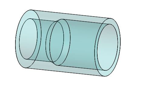
Tapers can be a real bugger to measure. The two cylinder method works. A short cylinder with appropriate slightly different internal diameters is used. A dial indicator is set up to measure the position of the tailstock e4nd of the cylinder when the cylinder is fitted to the taper. The indicator position is recorded and the cylinder is reversed and its position measured with the indicator. The difference in the diameter, coupled with the difference in the indicator readings and a little trigonometry will give you the taper. Measuring the diameter of the large end of a taper is a piece of cake, the small end, not so easy. If possible, I will turn a cylinder on the small end of the taper with a diameter equal to the small diameter of the taper. I will then cut off the cylinder at the intersection with the taper.

Internal bores can be measured with gage pins, bore gages, or telescoping gages. Internal tapers can be measured with ball bearings. Having a mating part to the taper is also useful in determining correct machining. And of course, depth gages for bore depths.
 
Thanks guys a good place to start. I just have a hf cheap cheap dial ind and mag base now, the list keeps growing. Longer indicator-check. Also just started thinking of modifying cheap digital caliper, that might work too.


Sent from my iPhone using Tapatalk
 
Before I had a DRO I used 1" & 2" dial indicators with mag backs mounted on the way like most eveyone commonly does. Well I still use a DI for threading.

Even though I had a 2" I found myself using the 1" more. Slower having to measure & move the indicator for lengths longer than the DI's travel but it did the job well.

Another option is a Trav-A-Dial but you have to be very patient to find one for a good price.
 
Not adding too much here, but +1/2/3 on the 2" travel dial indicator on a magnetic base. Bought mine from CDCO for probably under $30. I face both ends of the part and record the overall length. Then touch the tool bit to the end of part sticking out of the chuck and lock the carriage. Make sure the compound rest is turned into the work also. Then set the indicator on the lathe bed and zero the scale. Naturally, the indicator should be as parallel to the bed as possible.

Bruce
 
It depends upon what you are trying to measure, its size, and the required accuracy. Diameters are easily measured, turned lengths, not so much. If I were necking down a piece to a shoulder (like a top hat), I would be inclined to set up a carriage stop corresponding to the top of the brim of the top hat. I would then place a spacer of the exact length of the neck between the stop and the carriage. Now the carriage will stop at the top of the neck. This is particularly useful if making multiple parts as there isn't a need for a lot of measurement checks.

If I was facing a bar to length, I would use a spindle stop. Place thwe spindle stop in the bore of the spindle. Set the compound so its travel is parallel to the spindle axis. Make a trial oversized cut with the work tight to the stop and the carriage locked down.. Pull the work out of the lathe and measure, determine a corrective cut and adjust the compound accordingly. For more accuracy, the compound can be set at an angle of 84.3º to the spindle axis so each inch of compound travel move .1" in the direction parallel to the spindle axis.

It is also possible to face a bar to length by cutting it slightly oversized, removing and measuring, and then touching off the cutting tool on the previously cut face and adjust the tool position as required.

Tapers can be a real bugger to measure. The two cylinder method works. A short cylinder with appropriate slightly different internal diameters is used. A dial indicator is set up to measure the position of the tailstock e4nd of the cylinder when the cylinder is fitted to the taper. The indicator position is recorded and the cylinder is reversed and its position measured with the indicator. The difference in the diameter, coupled with the difference in the indicator readings and a little trigonometry will give you the taper. Measuring the diameter of the large end of a taper is a piece of cake, the small end, not so easy. If possible, I will turn a cylinder on the small end of the taper with a diameter equal to the small diameter of the taper. I will then cut off the cylinder at the intersection with the taper.

Internal bores can be measured with gage pins, bore gages, or telescoping gages. Internal tapers can be measured with ball bearings. Having a mating part to the taper is also useful in determining correct machining. And of course, depth gages for bore depths.

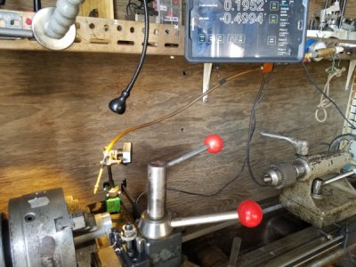
Great information RJ. I think I get what you are talking about with all but the two cylinder taper method. I get the concept but it's a bit past my knowledge base. Time to up the ginseng and work out the old brain cells. Constant learning, Another cool part about this hobby.


Sent from my iPhone using Tapatalk
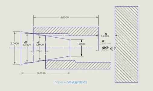
A taper angle can be defined by the two diameters separated by a known distance. A cylinder of convenient length and two different bore diameters appropriate to the taper being measured is made. The small bore end of the cylinder is fitted to taper, using care to square it to the spindle axis, and a dial indicator is zeroed on the tailstock end of the cylinder. The cylinder is removed and reversed and another dial indicator reading of the tailstock end of the cylinder is made. The difference between the two indicator readings is recorded as "l2 -l1" . The taper in in./in. or mm/mm is (d2-d1)/2*(l2-l1). %Tom Lipton of Ox Tools has a good video on this measurement (as well as a lot of other good videos).
One caution would be since you are usually dealing with small differences, it is important that careful measurements be made. Of I were going this route, I would "calibrate" the difference in the cylinders with a known taper, say a Morse or Jacobs taper, rather than trying to accurately measure the diameters. The length of the cylinder doesn't enter into the calculation so as long as the ends are square and there is a sharp edge on the bore, you should have a good tool.

Taper Cylinder.JPG Taper  Measurement.JPG
 
Back
Top