- Joined
- Feb 1, 2015
- Messages
- 9,947
I have recently begun the task of tuning up my Tormach PCNC 770. Part of the process is adjusting the ball screw thrust bearing preloads. Two methods for adjusting are recommended: measuring backlash or free play as the bearing play is removed, and estimating the amount of torque needed to rotate the ball screw.
In talking with one of the Tormach staff at their open house recently, he suggested the two finger method for determining the torque. It seemed like there should be a better way to do this. Here is what I came up with.
I realized that I would need an extremely sensitive torque wrench to accomplish the task. My sensitive torque wrench effectively starts at 5 ft-lbs. (60 inch lbs.). Additionally, it is the click type which is not conducive to the measurements needed. Dial type torque wrenches are available but rather pricey and I wanted it now.
Several years ago, I had to measure some low value torques and I accomplished this by using a known length lever and a force gauge. The problem with that method is that it is difficult to rotate a shaft and keep the gauge perpendicular to the lever so that a cosine error is avoided. The light bulb went on. If I replaced the lever with a disk with a string wound on it, the gauge would always be perpendicular to the "lever". I could unwind the string using the gauge and get an average reading over several revolutions. Rewind the string and get some additional readings or wind it backwards to read in the reverse rotation.
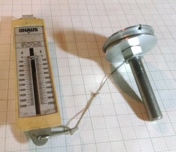
I selected a 1/2" shaft which matched the stepper motor shaft diameter and drilled and tapped a 1/4-20 UNC hole in one end. I then machined a 2" diameter flat pulley from a piece of 1/2" thick aluminum, drilled a hole for the 1/4-20 screw, and bored a counterbore to accept the 1/2" shaft. I finished by drilling a small diagonal hole on the side of the pulley to anchor the string. I assembled the tool and attached a length of Nylon line to complete the assembly. The tool and scale used are shown in the first picture.
The 2" pulley gives me a 1" lever arm so whatever the units the scale used to measure force is the torque reading in inch-units. My scale was in grams which I converted to ounces and my values were in in-oz.
I replaced my x axis stepper with the tool and loosened the x axis gibs. The force reading was about 600 g-f which is equivalent to 21 in-oz. of torque with my setup. I then back the preload off and got essentially the same torque reading. Finally, I tightened the preload for a reading of 38 in-oz. of torque. This corresponds to the preload providing an additional 17 in-oz. of torque.
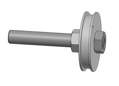
In making my adjustments, I found it necessary to secure the ball screw shaft assembly with a pair of Vise-Grips on the shaft of my new tool. (The manual recommends using them on the coupling but I couldn't bring myself to do that.) I then bored out a 1/2-13" hex nut and welded it to the shaft of my tool so that I could use a box wrench instead of the Vise-Grips. In thinking about the construction, I then came up with a simpler way to make the tool. A suitable length rod, the diameter matching the ball or lead screw shaft, is threaded to take a standard nut. A nut is installed on the shaft. It is preferable to fix it with Loc-Tite or similar product as it is potentially exposed to considerable torque. A rough cut disk is cut from 1/2" plate and bored for the shafting and then mounted on the shaft and secured with a second nut. The assembly is then turned to finished dimensions. Finally, a small hole is drilled through the pulley for the string. A suggested assembly is shown in the second picture.
The tool worked very well for measuring torque load. I can see this as a suitable tool for adjusting gibs on both manual and CNC mills and on lathes cross feeds and compounds.
Bob


 .
.