- Joined
- Jun 23, 2011
- Messages
- 786
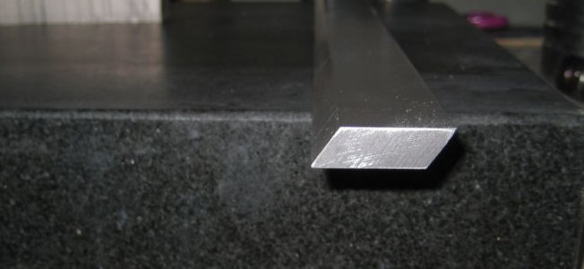
The gib that came with my PM-45 was a disgrace. I was not scraped and looked like it was "tuned up" with a belt sander. After several hours of scraping, I got the fit much better but it ended up too thin thus requiring it to be shimmed. The shimming was done by soft soldering a brass shim to the backside and surface grinding it true. While the machine was definitely better performaing after the mod, the brass shim is a band-aid at best. So, I decided to make a new gib from scratch.
The first step was sourcing the material. I chose a continuously cast iron product called Durabar. I chose G2 grade, pearlitic. Knowing I needed a 11.25" gib, I ordered up a 16" length so I'd be able to scrape it to fit perfectly, then simply cut it off at the right places after it was test fit.
When the material arrived, I face milled it square on two sides.
The next step was determining the taper. I suspected since this is an import lathe it would use the "defacto" standard of a 1 in 100 taper. This was not the case. By performing many different measurements I got a lot of data that indicated the taper was 1 in 125.
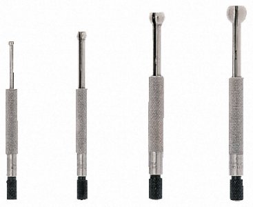
It seems the best way to make this measurement this is to install the slide without the gib then use an expanding small hole gauge to measure the gap between the inside surface of the slide and the ways at each end. Knowing the distance between the two measurement points it was fairly easy to trig out the angle (0.4584 degrees).
A small hole gauge set:
Knowing the pertinent measurements, I marked out the Durabar with the taper and rough cut it on the bandsaw about 50 thou thicker than needed.
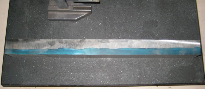
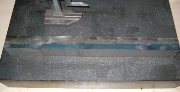
I didn't take a picture of the rough cut gib, but here's the left over durabar after cutting... Plenty of stock left for other projects.
Next, I just used an end mill to sqaure up the two thin sides.
After pontificating for a while about how to machine the saw cuts away and end up with a precise taper, I settled on the following method...
I got some beefy scrap aluminum extruded L-stock and milled it flat and square. I then installed two vises onto the mill table (both were not the same, but it worked out anyway), aligned each master jaw and clamped the L-stock into the vises with one flat side facing up. The trick is to now position the L-stock in the vises and adjust the Z position of the L-stock to achieve the desired taper. I roughed the position with a simple magnetic base angle gauge. Final adjustment was done with a dial test indicator so I got exactly .008 of Z for every 1.000" of Y table travel. This is 1 in 125...
Now, I simply put some CA glue on the L-stock and stuck the machined side of the Durabar onto L-stock and gently tapped it to squeeze out extra CA.
Then, by light cuts with the face mill I was able to machine it down to the required thickness (with each required thickness measurement centered on the bar). The durabar gives a very nice surface finish! Assuming the taper is 100% correct, then minimal scraping will be required...
At this point, I'm left with a flat bar with a taper on one side. However, this is going on a dovetailed way, so the short sides need to be angled and parallel to each other...
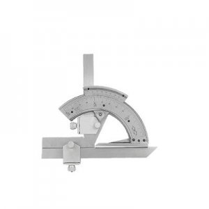
Now I needed to know the correct angle. I made a bunch of measurements of the ways with a vernier protractor and determined to angle to be 35° 10'. Odd to say the least. I was hoping it would be 30°, 45° or 60° so it could be simply cut with a dovetail mill. Why the odd angle I cannot guess. I double checked the calibration of the protractor in the inspection lab at work and found it to be spot on. Now things got more complicated....
I'll digress here and show the vernier protractor... This is the same unit touted (and rightly so) by Guy Lautard. You can get them on eBay for about $40.
Getting back to the angle cut...
My mill head cannot tilt forward and back, also I don't have enough Y travel to machine all 16". So more pontificating was in order. The best method I could come up with would be to remove the slide from the mill, install the gib into it with some sort of spreader clamp and simply mill it down parallel to the slide. Unfortunately, this required a second milling machine! We have several Bridgeports at work, but the building is closed for the Holidays until after the new year.
I thought up a few alternate methods, but kept coming back to some kind of tilt table arrangement. Unfortunately, the tilt table is only 10" wide and the gib is 16" long... Unavoidably I'd have to cut the angles for 10-11 inches, then reposition the gib for the remaining length... Trying to machine the overhanging parts would end up with so much chatter that I'd likely end up with a poor finish at best (and chip up the carbide end mill I has slated for use).
I might have gotten away with centering the gib on the tilt table which would leave only about 2.5" overhanging on each side. But, this would require removing my mill vise and moving the tilt table to the center of the table so I didn't run out of X travel. I didn't want to do this since it is indicated in and I wasn't sure if I would need to use the vise for internediate operations and fixture making. As it turned out, I did need to use the vise.
I put the tilt table on the surface plate and set it to the correct angle using the same vernier protractor used to measure the dovetails. I then mounted the tilt table onto the mill bed and sqaured it up with a DTI.
After staring at the setup for a bit, I decided a fence for the tilt table would be preferable to indicating the gib each time I repositioned it. I took some scrap aluminum jig plate and machined it to be the same thickness as the T slots on the tilt table. Then I stuck it down into the outermost slot and used some strap clamps for good measure. I now had a decent fence at a right angle to the tilt table surface. It ended up being parallel to the mill's Y travel within a couple thou over 6". This is good enough since the precision to ensure each gib short side is parallel will be attained later (I'll describe how further in).
This photo is really from further along in the process, but it gives a good idea of the setup.
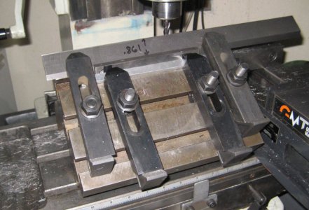
Now all I had to do was bank one of the short edges against the fence and side mill the edge of the gib overhanging the tilt table. Care is needed here as the gib can be mounted four ways and only two are right. I'll leave this to thought on the reader's part.
After the angle was cut, I verified it with the vernier protractor. Now I needed to cut the other side. Banking the cut edge of the gib fence against the fence really isn't a great idea since the sharp edge of the cut side would be against the fence. Line contact not a recipe for precision...
So, I simply used the setup to mill the fence to the right angle and make it perfectly aligned with the mill. Great idea I thought, but it prevented the gib from overhanging enough to get it to the required dimension without running the mill into the tilt table. The fix was easy, or so I thought. I'd just stack some parallels to make up the extra material. I made a trial cut using this method and found the gib to have sides that weren't paralle to each other... Huh?
At first I thought the parallels were leaning over as the gib was clamped down. So I shimmed them in so they couldn't move. I made another light cut. Nope. Still not parallel. It turns out my parallels are parallel with regard to their thickness, only their height. Some had as much as 3 thou of taper!.
Ok. Looks like I need to whip up a suitable vertical fence... I had a scrap of .375 steel ground plate. I just cut off a strip, deburred, verified it was of uniform thickness and stuck it down into the groove in the aluminum fence and shimmed it in tight (see photos).
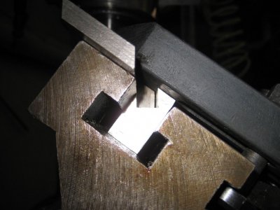
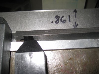
After taking a trial cut, I ended up with about 0.001 of taper over 10". I am looking for less than 0.003 over the 16", so I'm where I want to be.
Now, all I have to do Is complete the machining to get the desired dimension of 0.861, install it, scrape it in and cut it to the right final length. I'll post a follow up picture of the completed gib along with the fit up process when I'm done.
John


The first step was sourcing the material. I chose a continuously cast iron product called Durabar. I chose G2 grade, pearlitic. Knowing I needed a 11.25" gib, I ordered up a 16" length so I'd be able to scrape it to fit perfectly, then simply cut it off at the right places after it was test fit.
When the material arrived, I face milled it square on two sides.
The next step was determining the taper. I suspected since this is an import lathe it would use the "defacto" standard of a 1 in 100 taper. This was not the case. By performing many different measurements I got a lot of data that indicated the taper was 1 in 125.
It seems the best way to make this measurement this is to install the slide without the gib then use an expanding small hole gauge to measure the gap between the inside surface of the slide and the ways at each end. Knowing the distance between the two measurement points it was fairly easy to trig out the angle (0.4584 degrees).
A small hole gauge set:

Knowing the pertinent measurements, I marked out the Durabar with the taper and rough cut it on the bandsaw about 50 thou thicker than needed.
I didn't take a picture of the rough cut gib, but here's the left over durabar after cutting... Plenty of stock left for other projects.


Next, I just used an end mill to sqaure up the two thin sides.
After pontificating for a while about how to machine the saw cuts away and end up with a precise taper, I settled on the following method...
I got some beefy scrap aluminum extruded L-stock and milled it flat and square. I then installed two vises onto the mill table (both were not the same, but it worked out anyway), aligned each master jaw and clamped the L-stock into the vises with one flat side facing up. The trick is to now position the L-stock in the vises and adjust the Z position of the L-stock to achieve the desired taper. I roughed the position with a simple magnetic base angle gauge. Final adjustment was done with a dial test indicator so I got exactly .008 of Z for every 1.000" of Y table travel. This is 1 in 125...
Now, I simply put some CA glue on the L-stock and stuck the machined side of the Durabar onto L-stock and gently tapped it to squeeze out extra CA.
Then, by light cuts with the face mill I was able to machine it down to the required thickness (with each required thickness measurement centered on the bar). The durabar gives a very nice surface finish! Assuming the taper is 100% correct, then minimal scraping will be required...
At this point, I'm left with a flat bar with a taper on one side. However, this is going on a dovetailed way, so the short sides need to be angled and parallel to each other...
Now I needed to know the correct angle. I made a bunch of measurements of the ways with a vernier protractor and determined to angle to be 35° 10'. Odd to say the least. I was hoping it would be 30°, 45° or 60° so it could be simply cut with a dovetail mill. Why the odd angle I cannot guess. I double checked the calibration of the protractor in the inspection lab at work and found it to be spot on. Now things got more complicated....
I'll digress here and show the vernier protractor... This is the same unit touted (and rightly so) by Guy Lautard. You can get them on eBay for about $40.

Getting back to the angle cut...
My mill head cannot tilt forward and back, also I don't have enough Y travel to machine all 16". So more pontificating was in order. The best method I could come up with would be to remove the slide from the mill, install the gib into it with some sort of spreader clamp and simply mill it down parallel to the slide. Unfortunately, this required a second milling machine! We have several Bridgeports at work, but the building is closed for the Holidays until after the new year.
I thought up a few alternate methods, but kept coming back to some kind of tilt table arrangement. Unfortunately, the tilt table is only 10" wide and the gib is 16" long... Unavoidably I'd have to cut the angles for 10-11 inches, then reposition the gib for the remaining length... Trying to machine the overhanging parts would end up with so much chatter that I'd likely end up with a poor finish at best (and chip up the carbide end mill I has slated for use).
I might have gotten away with centering the gib on the tilt table which would leave only about 2.5" overhanging on each side. But, this would require removing my mill vise and moving the tilt table to the center of the table so I didn't run out of X travel. I didn't want to do this since it is indicated in and I wasn't sure if I would need to use the vise for internediate operations and fixture making. As it turned out, I did need to use the vise.
I put the tilt table on the surface plate and set it to the correct angle using the same vernier protractor used to measure the dovetails. I then mounted the tilt table onto the mill bed and sqaured it up with a DTI.
After staring at the setup for a bit, I decided a fence for the tilt table would be preferable to indicating the gib each time I repositioned it. I took some scrap aluminum jig plate and machined it to be the same thickness as the T slots on the tilt table. Then I stuck it down into the outermost slot and used some strap clamps for good measure. I now had a decent fence at a right angle to the tilt table surface. It ended up being parallel to the mill's Y travel within a couple thou over 6". This is good enough since the precision to ensure each gib short side is parallel will be attained later (I'll describe how further in).
This photo is really from further along in the process, but it gives a good idea of the setup.

Now all I had to do was bank one of the short edges against the fence and side mill the edge of the gib overhanging the tilt table. Care is needed here as the gib can be mounted four ways and only two are right. I'll leave this to thought on the reader's part.
After the angle was cut, I verified it with the vernier protractor. Now I needed to cut the other side. Banking the cut edge of the gib fence against the fence really isn't a great idea since the sharp edge of the cut side would be against the fence. Line contact not a recipe for precision...
So, I simply used the setup to mill the fence to the right angle and make it perfectly aligned with the mill. Great idea I thought, but it prevented the gib from overhanging enough to get it to the required dimension without running the mill into the tilt table. The fix was easy, or so I thought. I'd just stack some parallels to make up the extra material. I made a trial cut using this method and found the gib to have sides that weren't paralle to each other... Huh?
At first I thought the parallels were leaning over as the gib was clamped down. So I shimmed them in so they couldn't move. I made another light cut. Nope. Still not parallel. It turns out my parallels are parallel with regard to their thickness, only their height. Some had as much as 3 thou of taper!.
Ok. Looks like I need to whip up a suitable vertical fence... I had a scrap of .375 steel ground plate. I just cut off a strip, deburred, verified it was of uniform thickness and stuck it down into the groove in the aluminum fence and shimmed it in tight (see photos).


After taking a trial cut, I ended up with about 0.001 of taper over 10". I am looking for less than 0.003 over the 16", so I'm where I want to be.
Now, all I have to do Is complete the machining to get the desired dimension of 0.861, install it, scrape it in and cut it to the right final length. I'll post a follow up picture of the completed gib along with the fit up process when I'm done.
John


