- Joined
- Dec 27, 2019
- Messages
- 18
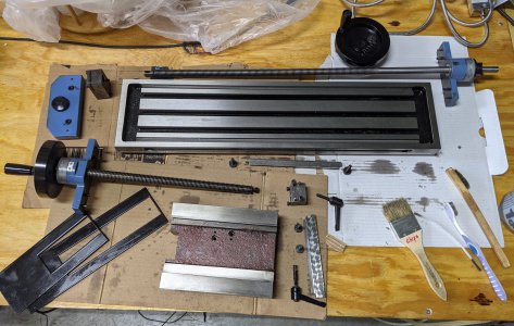
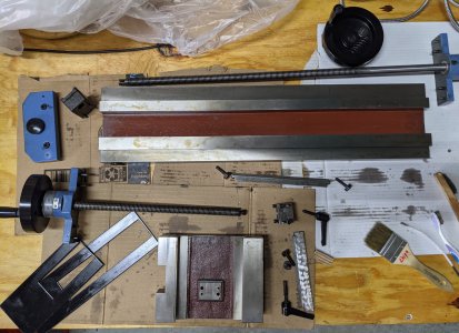
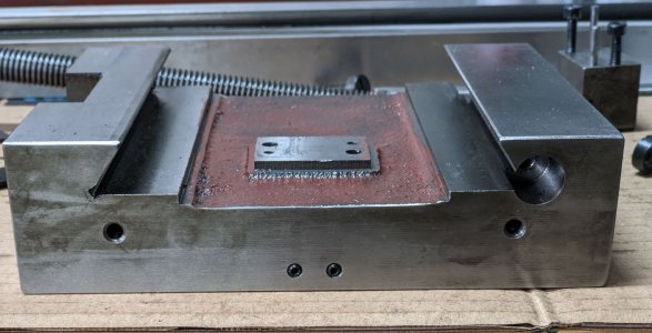
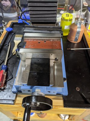
I started a DRO/scales upgrade on my LMS 5500 and decided to completely tear down the cross slide to make it easier to drill/tap and to solve some issues. I cleaned the mill when I got it without doing this so I figured it was time to see how the cross slide was constructed, adjusted, and what goop was still hiding in there. First some pictures for those who have not taken one apart.


First question: What are the 2 holes on front and back of the Y-slide used for? (The front 2 holes have grub screws to cover the hole and appear to serve no purpose as the holes are blind.

I'm curious if it is for some accessory.
Second Question:
The X-slide (looking at the front) has the lock nut attached to the left side of the Y-slide.
When I would crank the X-slide all the way to the LEFT, the table would go to the very end.
When I would crank the X-slide all the way to the RIGHT, it would bind about 2 inches from the very end.
My suspicions that the slide screw was out of alignment was confirmed when I removed it and the slide would go all the way to both LEFT and RIGHT.
*** Has anyone had this issue? If so, what did you adjust to line things up?
The blue end plates have alignment pins and lock nut has little movement range with the 2 bolt holes.
Third Question:
Before disassembling, I decided to indicate the X-slide. As I cranked, I saw visible movement. I tightened the jibs until it went away.
What didn't go away was a little more than 0.003" movement toward the front with the indicator located on the RIGHT side of the mill Z-column.
*** When tightening the gibs (they tighten on both ends), can then cause mis-alignment if not not tightened correctly? Also, could this movement just be a symptom of the 0.003" deflection is question 2?
I'm still relatively new to this and just know that they should only be tight enough to stop movement and no more. Feel free to educate me.


First question: What are the 2 holes on front and back of the Y-slide used for? (The front 2 holes have grub screws to cover the hole and appear to serve no purpose as the holes are blind.

I'm curious if it is for some accessory.
Second Question:
The X-slide (looking at the front) has the lock nut attached to the left side of the Y-slide.
When I would crank the X-slide all the way to the LEFT, the table would go to the very end.
When I would crank the X-slide all the way to the RIGHT, it would bind about 2 inches from the very end.
My suspicions that the slide screw was out of alignment was confirmed when I removed it and the slide would go all the way to both LEFT and RIGHT.
*** Has anyone had this issue? If so, what did you adjust to line things up?
The blue end plates have alignment pins and lock nut has little movement range with the 2 bolt holes.
Third Question:
Before disassembling, I decided to indicate the X-slide. As I cranked, I saw visible movement. I tightened the jibs until it went away.
What didn't go away was a little more than 0.003" movement toward the front with the indicator located on the RIGHT side of the mill Z-column.
*** When tightening the gibs (they tighten on both ends), can then cause mis-alignment if not not tightened correctly? Also, could this movement just be a symptom of the 0.003" deflection is question 2?
I'm still relatively new to this and just know that they should only be tight enough to stop movement and no more. Feel free to educate me.
Last edited:

