When I built my mill a couple of years ago I struggled with wiring my limit switches in series. My intent was to use one input on the BoB so I would have a couple for future expansion. That didn't work out so I ended up wiring each switch to and individual input. It's been working just fine until yesterday when I decided I wanted a Z axis zero tool setter. This is where my problems begin.
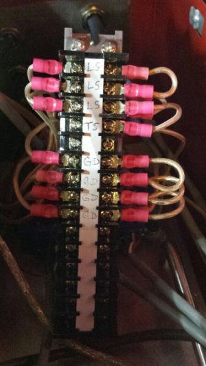
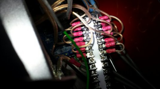
Here's a picture of my limit switch/tool setter terminal block. The three wires on the upper left are the X, Y and Z plus (+) wires from the limit switches. Each of the four upper right terminals are jumpered with one wire going to an input terminal on the BoB (pin 10 on the Input Signal tab in Ports and Pins). I checked continuity and all is good. You will note that the tool setter plus (+) wire is not connected nor is it connected at the BoB. One step at a time.
The four wires on the lower left are ground wires (-) for the X, Y, and Z axis and the E-Stop circuit. The E-Stop plus (+) is wired to pin 13 on the BoB. The wires on the lower right are also jumpered with one wire going to the ground terminal on the BoB. Checked continuity and it is good across all terminals.

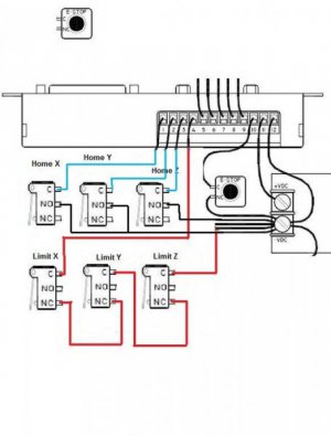
I enabled all limit and home switches on the Input Signal screen and set them to pin 10. As I said above the E-Stop is set to pin 13. The E-Stop works. I checked and am getting 5VDC across pin 10 and the BoB ground terminal but nothing at the terminal block. As a reality check I unwired all the switches and wired in just one and it worked. I can trip the circuit and home the one axis.
All this being said what am I missing or doing wrong? I'd like to get this problem solved so I can continue with wiring in the tool setter.
Tom S.
Here's a picture of my limit switch/tool setter terminal block. The three wires on the upper left are the X, Y and Z plus (+) wires from the limit switches. Each of the four upper right terminals are jumpered with one wire going to an input terminal on the BoB (pin 10 on the Input Signal tab in Ports and Pins). I checked continuity and all is good. You will note that the tool setter plus (+) wire is not connected nor is it connected at the BoB. One step at a time.
The four wires on the lower left are ground wires (-) for the X, Y, and Z axis and the E-Stop circuit. The E-Stop plus (+) is wired to pin 13 on the BoB. The wires on the lower right are also jumpered with one wire going to the ground terminal on the BoB. Checked continuity and it is good across all terminals.

I enabled all limit and home switches on the Input Signal screen and set them to pin 10. As I said above the E-Stop is set to pin 13. The E-Stop works. I checked and am getting 5VDC across pin 10 and the BoB ground terminal but nothing at the terminal block. As a reality check I unwired all the switches and wired in just one and it worked. I can trip the circuit and home the one axis.
All this being said what am I missing or doing wrong? I'd like to get this problem solved so I can continue with wiring in the tool setter.
Tom S.


