- Joined
- Dec 6, 2015
- Messages
- 828
I am starting a thread that I can potentially reference about "gears". First, I'll throw the basic formula for calculating gear pitch (specifically "diametral" pitch) for anyone who is trying to determine what kind of gear that they have.
Using change gears to cut threads is also a simple formula (I am oversimplifying it specifically for the imperial South Bends, but anyone can post an added formula) :
I'll tackle first the identification of gears. From my ugly, not-so-original green Heavy 10L, there are the following readily-accessible gears.
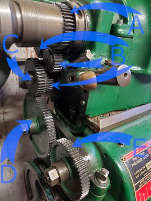
"A" is the spindle gear. This one is not easily replaced, and sits directly on the spindle. On the South Bend Heavy 10 (10L), this gear is an 18 DP gear. The one shown here is the longer one for the hand-lever collet attachment - most will not quite look like this, but they will all be on the spindle.
"B" are the "reversing mechanism gears. These gears must be the same pitch as the spindle gear because they interface with it. Moving the lever simply introduces another gear into the chain which causes the gears to spin the opposite direction down stream of this mechanism.
"C" is often referred to as the "stud" gear. This is because it sits on the same stud as the final reverse gear. On the South Bend Junior and Heavy 10, these gears are 16 DP. On regular 9" lathes and 10k (10" lights), these will all be 18 DP. This is easily replaced by removing the nut keeping it captive, but beware, it is keyed to the shaft. Don't lose that key.
"D" is an "idler" gear. This can sometimes be shown as a "compound" gear. It sits on the banjo in the groove, and allows the banjo to spin until the gears all mesh. The gear teeth here to not matter unless you are using a compound gear. Because this interfaces with the stud gear and the screw gear, it must be the same pitch as those, which means this is a 16 DP gear on the South Bend Heavy 10 and Junior models. On regular 9" lathes and 10k (10" lights), these will all be 18 DP.
"E" is called the "screw gear", because it is what is driving the lead screw. Again, because it interfaces with the stud and idler gears, it has to be the same pitch, meaning 16 DP on the junior's and heavy 10's, or 18DP on the 9/10k's.
On my Junior, the reversing mechanism looks like the following with the spindle gear at the top. On the bottom stud, you can see two gears (the 16 tooth is the closest one to the camera, the one behind it is part of the reversing mechanism) :
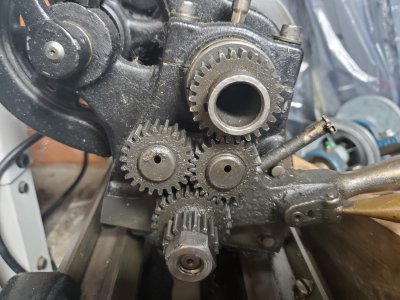
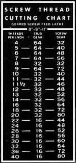
For the purpose of threading with change gears, the two gears are the stud ("C") and the screw gears ("E"). You will need to make sure you are not using the compound-type gear (or if you are, just make sure all three gears are in line so as not to introduce the idler's added gear). The "Junior" lathe has the following thread cutting chart for change gears :
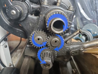
Here is a quick primer on the "reversing mechanism". Remember that a gear interfacing with the other has to have the interface surface moving in the same direction. It causes the gears to spin in opposite directions, and the reversing mechanism takes advantage of that. First, in the forward position :
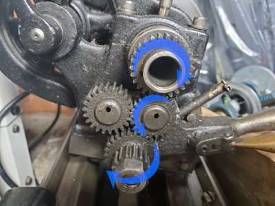
Then, in the "reversing" position (I was too lazy to get another picture of the lever moved) we introduce the back gear on the assembly, and it results in the following rotations:
If anyone else has added gear info they'd like to add, please do so. I'll take corrections on any guffaws I made, too.
DP (diametral pitch) = | number of teeth + 2 |
| diameter of the gear in inches |
Using change gears to cut threads is also a simple formula (I am oversimplifying it specifically for the imperial South Bends, but anyone can post an added formula) :
Thread Pitch = | # of Screw Gear Teeth * 8 |
| # of Stud Gear Teeth |
I'll tackle first the identification of gears. From my ugly, not-so-original green Heavy 10L, there are the following readily-accessible gears.

"A" is the spindle gear. This one is not easily replaced, and sits directly on the spindle. On the South Bend Heavy 10 (10L), this gear is an 18 DP gear. The one shown here is the longer one for the hand-lever collet attachment - most will not quite look like this, but they will all be on the spindle.
"B" are the "reversing mechanism gears. These gears must be the same pitch as the spindle gear because they interface with it. Moving the lever simply introduces another gear into the chain which causes the gears to spin the opposite direction down stream of this mechanism.
"C" is often referred to as the "stud" gear. This is because it sits on the same stud as the final reverse gear. On the South Bend Junior and Heavy 10, these gears are 16 DP. On regular 9" lathes and 10k (10" lights), these will all be 18 DP. This is easily replaced by removing the nut keeping it captive, but beware, it is keyed to the shaft. Don't lose that key.
"D" is an "idler" gear. This can sometimes be shown as a "compound" gear. It sits on the banjo in the groove, and allows the banjo to spin until the gears all mesh. The gear teeth here to not matter unless you are using a compound gear. Because this interfaces with the stud gear and the screw gear, it must be the same pitch as those, which means this is a 16 DP gear on the South Bend Heavy 10 and Junior models. On regular 9" lathes and 10k (10" lights), these will all be 18 DP.
"E" is called the "screw gear", because it is what is driving the lead screw. Again, because it interfaces with the stud and idler gears, it has to be the same pitch, meaning 16 DP on the junior's and heavy 10's, or 18DP on the 9/10k's.
On my Junior, the reversing mechanism looks like the following with the spindle gear at the top. On the bottom stud, you can see two gears (the 16 tooth is the closest one to the camera, the one behind it is part of the reversing mechanism) :

For the purpose of threading with change gears, the two gears are the stud ("C") and the screw gears ("E"). You will need to make sure you are not using the compound-type gear (or if you are, just make sure all three gears are in line so as not to introduce the idler's added gear). The "Junior" lathe has the following thread cutting chart for change gears :

Here is a quick primer on the "reversing mechanism". Remember that a gear interfacing with the other has to have the interface surface moving in the same direction. It causes the gears to spin in opposite directions, and the reversing mechanism takes advantage of that. First, in the forward position :

Then, in the "reversing" position (I was too lazy to get another picture of the lever moved) we introduce the back gear on the assembly, and it results in the following rotations:

If anyone else has added gear info they'd like to add, please do so. I'll take corrections on any guffaws I made, too.
