Lathe Motor Question

Seuss54

Registered
Registered
Joined
Mar 17, 2024
Messages
19
I recently acquired a Southbend 14.5" lathe about 2 months ago and I finally was able to get it into my garage this past weekend. In my excitement I never thought to look at the motor (it was replaced by the previous owner) and I just assumed it was a 220V 3phase motor as that's what he told me. Now that I've got him home and I've been getting ready to wire it up I thought I should see whats down there and I think he actually put a 1 phase motor in. Electrical work is one of the few things I am willing to admit I have 0 knowledge and want to be absolutely careful with so any help would be appreciated.

The motor is a Marathon Electric Catalog No. F15E1. I guess it's a farm motor based on the ID tag. My questions are 1: Do I need to change this out for a 3 phase motor? 2: Will this affect the lathe's performance and how so? 3: The tag says 115V/208-230V does that mean it will run on either 115 or the 208 to 230 range of voltage and I'm assuming higher voltage would be better?
 
I assume you have single phase power, 120/240VAC. Yes the motor is single phase input capacitor start motor. No you do not need to change it out for a 3 phase motor, try it and see hoe it works. Performance wise it shouldn't make a big difference, 3 phase can give a slightly better surface finish, has less issues with frequent start/stop cycles as well as more durable. Always allow the motor to stop before changing direction with a single phase motor, in some cases trying to switch directly from one direction to another the single phase motor will not change rotation. It is a dual voltage motor, yes you are better off running it on 230VAC, at 120VAC the peak current is close to 15A which may trip a standard socket. But you could get buy with 120VAC if that is all you have, you need to check the motor wiring as to the current voltage connections.
 

Attachments

  • F15E1.pdf
    349.7 KB · Views: 16
Agreed, single phase will work but as mksj said, the reversing isn't as smooth. I like to instantly reverse when doing operations like tapping, die threading, etc.
 
Check the wiring at the motor access before powering up as it could be 120 or 240 vac.

Motor position means limited space, camera helps.

If you can not see anything, either pull it out or test with 120 volts first.

Sent from my SM-G781V using Tapatalk
 
220 volt operation is preferable to 110 v- less current
 
Thank you for all your help! Unfortunately the cost to install a 220V outlet wayyy exceeds my budget right now so I'm going to give 120 a try. I do have some questions does anyone have some good resources on how to read the wiring diagram for the motor? Also can I just buy any power cord of amazon or do I need a specific gauge or anything like that?
 
mksj had the correct answer and the pdf he posted has the wiring diagrams.

Does the motor have a cord on it now?

If not, then take the cover off of the wiring box. There should be a diagram inside the cover.

For 120v single phase there are 3 wires involved. One is "hot" one is "neutral" and one is ground. The wiring diagram will probably call the "hot" wire "load". The ground will go to a ground screw or possibly a green wire inside the box.

On the cord end, Hot is Black, Neutral is White and Ground is Green. The diagram in the box will tell you which color wires till connect to where.

For a 15 amp circuit you want at least 14ga. wire. Larger is always better (up to a point) so go with a 12ga wire for your cord and you will be fine. I would go to a hardware store and buy the length of wire I wanted and a plug end and just make up a cord. Sometimes it is actually cheaper to buy a pre-made extension cord of the correct size and just cut off the female end, strip back the insulation and wire it to the motor.

You are going to want a switch between the wall plug and the motor.

Do you want the motor to be reversible or is one direction good enough for now? Setting up a reversing switch is a little more complicated but not all that bad with the proper diagrams to show what you need.

My SB 10K came with a new Dayton 1HP motor on it. The guy had tossed the 3PH motor it came with. :( and he didn't know how to wire a switch so you had to plug it in to run the lathe and unplug it to stop it. For initial testing, I plugged it into an outlet strip with a switch mounted on the bench so at least I had on and off. Eventually I wired in a drum switch so I have forward and reverse. Reverse is not used often but sometimes it is handy to have. I only had 120v available at the time. Since then I have rewired my entire shop with a new main panel and split the loads up to many different circuits. No more tripping breakers!

When I got the mill I wired in 220V for it and added a second circuit for the lathe. I just need to find time to convert the motor and drum switch over to 220 so I can get it off of the regular wall outlets.

Post a picture of the labels on the motor and the wiring diagram inside the connection box. I am sure we can then show you how to wire it up. Electricity at the residential level is really easy once you learn the basics.
 
I am supposed to fly back home tomorrow so I should be able to get some good photos of everything for you as long as the flight goes fine. Thanks for the help!
 
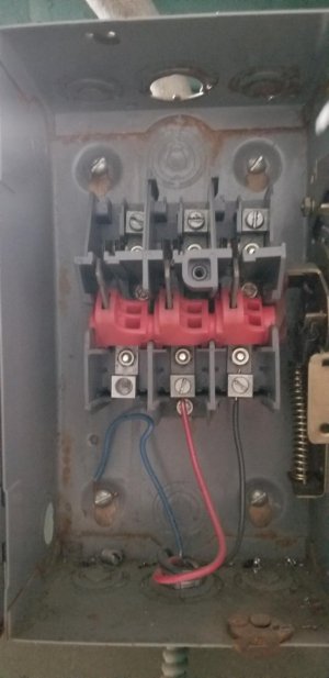
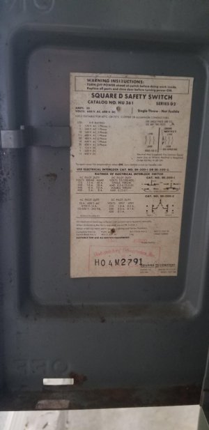
Pictures as requested, not sure exactly what I'm looking at but this is the box they have on the back of the machine. I'm also curious if I could put some kind of a start/stop switch that I could mount to the front for easy access to turn the machine off in case something happens. I don't know if that could be wired in with the plug?
 

Attachments

  • lathe2.jpeg
    lathe2.jpeg
    118.2 KB · Views: 7
  • Lathe1.jpeg
    Lathe1.jpeg
    118.2 KB · Views: 7
Back
Top