Kater’s Gravity Pendulum Project
Introduction
For centuries, a pendulum was the highest-precision way of measuring time by far, except for the motion of the stars themselves, which pendulums (in clocks) were calibrated against for scientific use. But if you moved a pendulum clock from London to France, for example, it would keep different time, because the accelerating force of gravity on Earth varied depending on where you were due to local changes in latitude, altitude, etc.
The formula for an ideal pendulum’s motion is T=2*Pi*SQRT(L/g), where T is the period (the time it takes for one back-and-forth swing), L is the length of the pendulum, and g is the local acceleration due to gravity. This formula thus allows for the measure of the acceleration of gravity on Earth.
No physical pendulum is ideal, though, and for a hundred years, scientists tried but failed to use simple pendulums to measure the local acceleration of gravity. That was until 1817, when Captain Henry Kater created a reversible pendulum: one that can be hung with the heavy side down or the heavy side up. By adjusting the pendulum until the period was the same when hung either way, the distance between pivots was found to be equivalent to L in the ideal-pendulum formula, and an accurate calculation of the local acceleration of gravity on Earth, “g”, could finally be made. His pendulums, and ones like them, were used around the world up until the 1950’s to measure local gravity and hence local underground geological features, to determine the shape of the Earth, to discover that the core of the Earth is iron, and so on.
This project attempts to recreate a Kater’s “gravity pendulum” as a learning exercise for machining basics (I am a newbie) as well as for the exercise in metrology (the measurement is quite difficult to make accurately), and just for the fun of recreating a historical scientific experiment.
Kater’s Pendulum
A drawing of Kater’s pendulum from 1817 is shown below (horizontally, without the mount), in front and side views (from Wikipedia, see "Kater's Pendulum"). Object “d” is a heavy brass bob, objects “a” on the left and right are triangular knife edges used as pivots to balance the pendulum from either end, objects “e” are “flags” used to time the pendulum’s period, and objects “b,c” are adjustment weights incorporating a fine screw adjustment. The main shaft between the pivots “a” is also heavy brass, and about 2 meters long.

The triangular knife-edge pivots, made from “Wootz” steel, rocked on hard agate plates for rigidity and low friction. Using knives as low-friction pivots is a technique from the clock world, used only in the most precise reference clocks, including in national standard clocks right up until the atomic-clock age.
The period of the Kater’s pendulum’s swing was measured by comparing it to the swing of a pendulum clock (calibrated against the motion of stars) via a “method of coincidences.” If the two periods are slightly different, then watching for coincidences of the two allows a vernier-like measurement. So, for example, if the two coincide once out of every hundred swings, then the two periods differ by (approximately) a part in 100.
Kater’s original measurement, made in London, was g=9.81158 m/s^2, yielding six digits of precision, though the 6th digit was likely dubious. The error on his measurement of the length of the pendulum used in this calculation (of a so-called “seconds pendulum” - one whose half-period equals 1 second) was no more than 7.1 micrometers (0.00028 inches). Thus you can see the level of precision he achieved, and this is actually required!
A 3-D Printed Gravity Pendulum Mock-Up
I first made a 3D-printed mock-up of a gravity pendulum to test the basic idea (photos attached), and I made a rather coarse measurements of g with it. This mock-up is a hybrid of Kater’s design and the subsequent Repsold-Bessel design (see Wikipedia). I placed the “agate plate” equivalent on the pendulum and the knives on the mount, rather than the opposite as seen in the figure. This means that only one set of knives are needed instead of two, eliminating one source of error, as knives may have different radii on their edges, which would subtly affect the period.
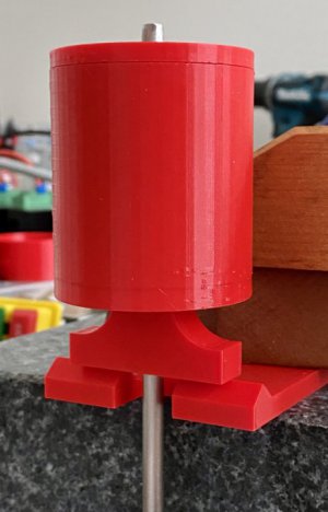
The shaft is 0.25” by 36”, made out of Invar, which is a nickel-iron alloy with an unusually-small coefficient of thermal expansion (the inventor of Invar received the Nobel Prize for it). The use of Invar substantially alleviates temperature as a factor, otherwise corrections or re-measurements would be needed if the temperature changes, since the length of the pendulum would change with it. This is a relatively expensive material that was purchased for the “real” version, but used in the mockup too.
The cylindrical feature is the bob, filled with lead shot and weighing about 1.25 lbs. Each end of the pendulum also has plastic anvils that ride on the plastic knife edges at the pivot. Because of the use of plastic knives and anvils, I expected friction to be high and hence the measurement quality to be low. However, I was surprised with how well the pendulum operated. Starting from a swing of about 5 degrees, I found that it oscillated for at least a half hour.
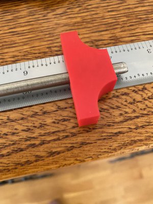
To calculate g, one needs the distance between the anvils (the equivalent length of the pendulum), the period of oscillation, and the distances between the anvils and the center of gravity (again see the Kater's pendulum page on Wikipedia). Using very rough methods, including measuring the period by eye and a stop-watch, and the distances with a simple scale to about 1/32”, I obtained a value for g that was within 1% of g for the nearest large city. Not great, and very far from Kater’s accuracy, but within expectations given the mockup’s limitations.
The Gravity Pendulum
After making the mock-up, I began work on the “real” pendulum. It is planned to consist of:
Goals
So what can be achieved? It’s not going to be possible to accurately measure local g to the degree of precision that modern instruments can. These days, that is done by dropping an object in a vacuum, and measuring the acceleration at which it falls (a direct measurement of g) via laser interferometry. I think I should be able to get another factor of 10-100 improvement over my mock-up’s value. However, I don’t have an accurate measurement of g for my immediate location to compare with, so its accuracy compared to reality could remain somewhat uncertain. (Kater didn't have anything to compare his measurement to either.)
What may be a better goal is to reach enough sensitivity to detect relatively small changes in g, rather than produce an absolute measurement of g. So, for example, measuring g multiple times with changes in altitude between measurements, perhaps between the bottom and top of a tall building. A conventional (non-reversible) pendulum actually suffices for relative measurements, but I’ll proceed with a reversible one and measure absolute g anyway.
The Bob
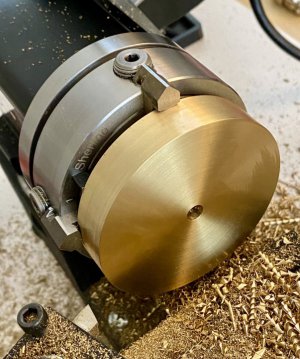
The bob (seen in an attached photo) is a relatively thin but wide brass disk (about 1/2 by 2.75”), and it’s intended to be mounted with the thin side along the shaft rather than the long side as in the Kater's pendulum figure above (in this case via a shrink or pressed fit). This places the weight as close to the pivot as reasonably possible, improving the pendulum’s performance. This is based on the Repsold-Bessel approach, which was an improvement on Kater’s pendulum.
The Anvils
I purchased some small pieces of flat borosilicate glass to use as anvils, but I’ve concluded that these are not going to work out, being too thick and too hard to cut to size. Instead, I intend to purchase small pieces of thin sapphire, pre-cut in a suitable size (pricey!). Meanwhile, I’ll use the glass to test methods of attachment, e.g. a trial with very thin CA glue.
Support Structure
I’ve also been considering concepts for the pendulum’s support structure. I’ve settled on using 1/4” square tool steel blanks as the knives, after polishing two adjoining sides. These would be mounted in angle blocks and possibly using 123-blocks to fix the angle-block’s mutual alignment. Unfortunately, there are incompatible mis-matches in hole geometries in the various blocks I acquired, and I haven’t yet figured out a satisfactory way to assemble it all. I may have to fabricate something instead of using off-the-shelf components.
It’s also necessary to consider how the assembly will be carried. It has to be rigidly suspended about a meter in the air. High rigidity is needed since any reacting movement during swings will sap energy from the pendulum plus corrupt the measurements. Indeed, Kater’s original mount was found to move by about a mm with each swing, and this had to be corrected. I was thinking of using heavy aluminum profile for supports, maybe with a cheap granite surface plate as a stable base, but I haven’t gotten far with this yet.
Time Measurement
Instead of Kater’s “method of coincidences”, I intend to use modern time-measurement techniques using an optical sensor and either an oscilloscope or a high-frequency counter. I thus purchased and tested an inexpensive optical sensor assembly, which I found to be good for better than 1 microsecond resolution for a single period, or better than a part in 10^6. Thus, the measurement of a single swing is already likely better than what Kater was able to achieve after his many days of exhaustive measurements. It can be improved further by averaging measurements, just as Kater did.
Length Measurement
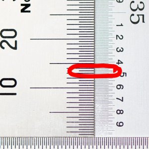
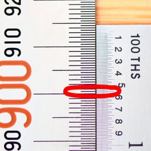
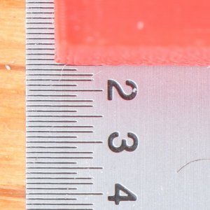
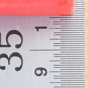
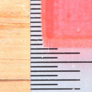
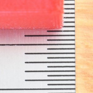
The biggest issue is how to measure the the distances between the anvils, measure the center of gravity, and to measure from both anvils to the center of gravity of the pendulum. These need near micrometer precision, especially the anvil-to-anvil measurement. I only have a 36” machinist’s scale to work with for now, and I can use a camera with a macro lens aimed at the anvils to help. Still, I'm limited to the accuracy that the scale can provide, which is not great: within 0.01” can be hoped for with a machinist’s scale over a distance of 36”.
Kater also only had scales available, and he used 3 to compare measurements between them. His scales were the most accurate available at the time, and he used a microscope to help make the measurements. But such scales were hand-made, and the definition of a meter wasn't even completely fixed back then. Indeed, the definition of a meter was even set as equal to the length of Kater’s seconds pendulum measurement for a while, in case the ultimate physical reference meter was destroyed. It’s not an accident that the length of a second’s pendulum is very close to 1 meter!
A high-resolution glass scale, e.g. a DRO mounted to a long-bed mill, and using a head-mounted microscope or macro camera to locate the anvils, would do much better. And if I feel like a 5 significant digit measurement of g is within reach, I could also contact a metrology lab to see if I can get a traceable measurement.
To Be Continued
The project will take a while, but I’ll come here to ask questions (remember, I’m an absolute newbie at machining) and provide updates. In the mean-time, here is a link to an early question and answer thread discussing this project, from which many great ideas by the community emerged:
Micron-level accuracy over a meter.
Thank you.
Introduction
For centuries, a pendulum was the highest-precision way of measuring time by far, except for the motion of the stars themselves, which pendulums (in clocks) were calibrated against for scientific use. But if you moved a pendulum clock from London to France, for example, it would keep different time, because the accelerating force of gravity on Earth varied depending on where you were due to local changes in latitude, altitude, etc.
The formula for an ideal pendulum’s motion is T=2*Pi*SQRT(L/g), where T is the period (the time it takes for one back-and-forth swing), L is the length of the pendulum, and g is the local acceleration due to gravity. This formula thus allows for the measure of the acceleration of gravity on Earth.
No physical pendulum is ideal, though, and for a hundred years, scientists tried but failed to use simple pendulums to measure the local acceleration of gravity. That was until 1817, when Captain Henry Kater created a reversible pendulum: one that can be hung with the heavy side down or the heavy side up. By adjusting the pendulum until the period was the same when hung either way, the distance between pivots was found to be equivalent to L in the ideal-pendulum formula, and an accurate calculation of the local acceleration of gravity on Earth, “g”, could finally be made. His pendulums, and ones like them, were used around the world up until the 1950’s to measure local gravity and hence local underground geological features, to determine the shape of the Earth, to discover that the core of the Earth is iron, and so on.
This project attempts to recreate a Kater’s “gravity pendulum” as a learning exercise for machining basics (I am a newbie) as well as for the exercise in metrology (the measurement is quite difficult to make accurately), and just for the fun of recreating a historical scientific experiment.
Kater’s Pendulum
A drawing of Kater’s pendulum from 1817 is shown below (horizontally, without the mount), in front and side views (from Wikipedia, see "Kater's Pendulum"). Object “d” is a heavy brass bob, objects “a” on the left and right are triangular knife edges used as pivots to balance the pendulum from either end, objects “e” are “flags” used to time the pendulum’s period, and objects “b,c” are adjustment weights incorporating a fine screw adjustment. The main shaft between the pivots “a” is also heavy brass, and about 2 meters long.

The triangular knife-edge pivots, made from “Wootz” steel, rocked on hard agate plates for rigidity and low friction. Using knives as low-friction pivots is a technique from the clock world, used only in the most precise reference clocks, including in national standard clocks right up until the atomic-clock age.
The period of the Kater’s pendulum’s swing was measured by comparing it to the swing of a pendulum clock (calibrated against the motion of stars) via a “method of coincidences.” If the two periods are slightly different, then watching for coincidences of the two allows a vernier-like measurement. So, for example, if the two coincide once out of every hundred swings, then the two periods differ by (approximately) a part in 100.
Kater’s original measurement, made in London, was g=9.81158 m/s^2, yielding six digits of precision, though the 6th digit was likely dubious. The error on his measurement of the length of the pendulum used in this calculation (of a so-called “seconds pendulum” - one whose half-period equals 1 second) was no more than 7.1 micrometers (0.00028 inches). Thus you can see the level of precision he achieved, and this is actually required!
A 3-D Printed Gravity Pendulum Mock-Up
I first made a 3D-printed mock-up of a gravity pendulum to test the basic idea (photos attached), and I made a rather coarse measurements of g with it. This mock-up is a hybrid of Kater’s design and the subsequent Repsold-Bessel design (see Wikipedia). I placed the “agate plate” equivalent on the pendulum and the knives on the mount, rather than the opposite as seen in the figure. This means that only one set of knives are needed instead of two, eliminating one source of error, as knives may have different radii on their edges, which would subtly affect the period.

The shaft is 0.25” by 36”, made out of Invar, which is a nickel-iron alloy with an unusually-small coefficient of thermal expansion (the inventor of Invar received the Nobel Prize for it). The use of Invar substantially alleviates temperature as a factor, otherwise corrections or re-measurements would be needed if the temperature changes, since the length of the pendulum would change with it. This is a relatively expensive material that was purchased for the “real” version, but used in the mockup too.
The cylindrical feature is the bob, filled with lead shot and weighing about 1.25 lbs. Each end of the pendulum also has plastic anvils that ride on the plastic knife edges at the pivot. Because of the use of plastic knives and anvils, I expected friction to be high and hence the measurement quality to be low. However, I was surprised with how well the pendulum operated. Starting from a swing of about 5 degrees, I found that it oscillated for at least a half hour.

To calculate g, one needs the distance between the anvils (the equivalent length of the pendulum), the period of oscillation, and the distances between the anvils and the center of gravity (again see the Kater's pendulum page on Wikipedia). Using very rough methods, including measuring the period by eye and a stop-watch, and the distances with a simple scale to about 1/32”, I obtained a value for g that was within 1% of g for the nearest large city. Not great, and very far from Kater’s accuracy, but within expectations given the mockup’s limitations.
The Gravity Pendulum
After making the mock-up, I began work on the “real” pendulum. It is planned to consist of:
- An Invar shaft, 0.25” by 36” (acquired)
- A fixed brass bob about 0.5 by 2.75”, weighing about 1.5 lbs (seen in an attached photo).
- Sapphire anvils attached directly to the bob.
- A brass bar holding anvils on the “light” side of the pendulum that can be positioned along the shaft to adjust the period.
- Sapphire anvils attached to the positionable brass bar.
- A positionable weight for fine center-of-gravity adjustments.
Goals
So what can be achieved? It’s not going to be possible to accurately measure local g to the degree of precision that modern instruments can. These days, that is done by dropping an object in a vacuum, and measuring the acceleration at which it falls (a direct measurement of g) via laser interferometry. I think I should be able to get another factor of 10-100 improvement over my mock-up’s value. However, I don’t have an accurate measurement of g for my immediate location to compare with, so its accuracy compared to reality could remain somewhat uncertain. (Kater didn't have anything to compare his measurement to either.)
What may be a better goal is to reach enough sensitivity to detect relatively small changes in g, rather than produce an absolute measurement of g. So, for example, measuring g multiple times with changes in altitude between measurements, perhaps between the bottom and top of a tall building. A conventional (non-reversible) pendulum actually suffices for relative measurements, but I’ll proceed with a reversible one and measure absolute g anyway.
The Bob
The bob (seen in an attached photo) is a relatively thin but wide brass disk (about 1/2 by 2.75”), and it’s intended to be mounted with the thin side along the shaft rather than the long side as in the Kater's pendulum figure above (in this case via a shrink or pressed fit). This places the weight as close to the pivot as reasonably possible, improving the pendulum’s performance. This is based on the Repsold-Bessel approach, which was an improvement on Kater’s pendulum.

The Anvils
I purchased some small pieces of flat borosilicate glass to use as anvils, but I’ve concluded that these are not going to work out, being too thick and too hard to cut to size. Instead, I intend to purchase small pieces of thin sapphire, pre-cut in a suitable size (pricey!). Meanwhile, I’ll use the glass to test methods of attachment, e.g. a trial with very thin CA glue.
Support Structure
I’ve also been considering concepts for the pendulum’s support structure. I’ve settled on using 1/4” square tool steel blanks as the knives, after polishing two adjoining sides. These would be mounted in angle blocks and possibly using 123-blocks to fix the angle-block’s mutual alignment. Unfortunately, there are incompatible mis-matches in hole geometries in the various blocks I acquired, and I haven’t yet figured out a satisfactory way to assemble it all. I may have to fabricate something instead of using off-the-shelf components.
It’s also necessary to consider how the assembly will be carried. It has to be rigidly suspended about a meter in the air. High rigidity is needed since any reacting movement during swings will sap energy from the pendulum plus corrupt the measurements. Indeed, Kater’s original mount was found to move by about a mm with each swing, and this had to be corrected. I was thinking of using heavy aluminum profile for supports, maybe with a cheap granite surface plate as a stable base, but I haven’t gotten far with this yet.
Time Measurement
Instead of Kater’s “method of coincidences”, I intend to use modern time-measurement techniques using an optical sensor and either an oscilloscope or a high-frequency counter. I thus purchased and tested an inexpensive optical sensor assembly, which I found to be good for better than 1 microsecond resolution for a single period, or better than a part in 10^6. Thus, the measurement of a single swing is already likely better than what Kater was able to achieve after his many days of exhaustive measurements. It can be improved further by averaging measurements, just as Kater did.
Length Measurement
The biggest issue is how to measure the the distances between the anvils, measure the center of gravity, and to measure from both anvils to the center of gravity of the pendulum. These need near micrometer precision, especially the anvil-to-anvil measurement. I only have a 36” machinist’s scale to work with for now, and I can use a camera with a macro lens aimed at the anvils to help. Still, I'm limited to the accuracy that the scale can provide, which is not great: within 0.01” can be hoped for with a machinist’s scale over a distance of 36”.
Kater also only had scales available, and he used 3 to compare measurements between them. His scales were the most accurate available at the time, and he used a microscope to help make the measurements. But such scales were hand-made, and the definition of a meter wasn't even completely fixed back then. Indeed, the definition of a meter was even set as equal to the length of Kater’s seconds pendulum measurement for a while, in case the ultimate physical reference meter was destroyed. It’s not an accident that the length of a second’s pendulum is very close to 1 meter!
A high-resolution glass scale, e.g. a DRO mounted to a long-bed mill, and using a head-mounted microscope or macro camera to locate the anvils, would do much better. And if I feel like a 5 significant digit measurement of g is within reach, I could also contact a metrology lab to see if I can get a traceable measurement.
To Be Continued
The project will take a while, but I’ll come here to ask questions (remember, I’m an absolute newbie at machining) and provide updates. In the mean-time, here is a link to an early question and answer thread discussing this project, from which many great ideas by the community emerged:
Micron-level accuracy over a meter.
Thank you.
Last edited:

