- Joined
- Oct 6, 2010
- Messages
- 699
I posted here (http://www.hobby-machinist.com/threads/questions-about-a-jet-lathe-gh-1340a.38860/) with some questions about this lathe that I found and liked but had no plan to get another project machine. I thought about it for a while but did it anyway. It is an illness!
I need to get this lathe usable as soon as possible as I have promised my only operational lathe to a friend as soon as this one is up and going. It will probably take longer than I was planned because of the cold weather as I have no heat in the shop. I promised myself last winter that I would get heat installed before it got cold again but I did not keep that promise.
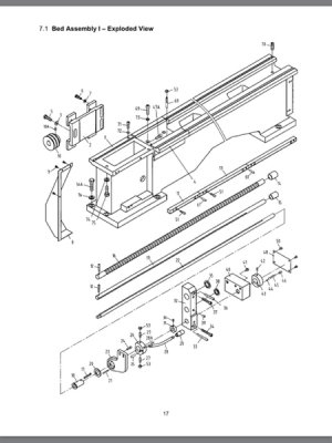
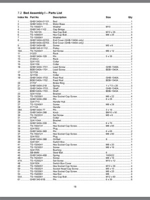
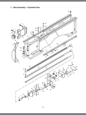
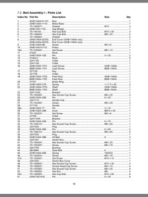
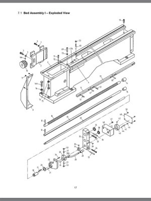
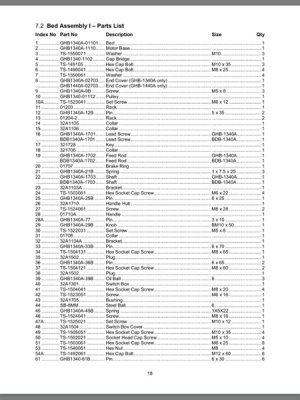
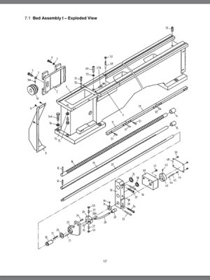
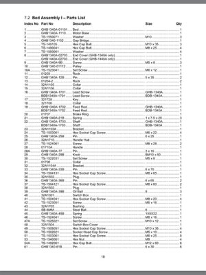
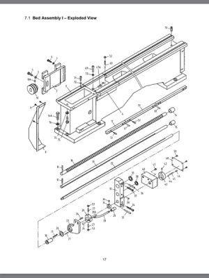
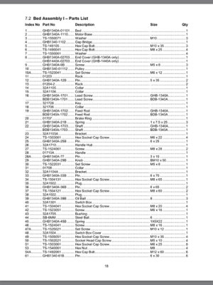
The dealer provided me with a hardcopy of the operator’s manual and a photocopy of the parts manual that matched the stock number on the machine tag. I have a little concern about the validity of these as they seem to show gray machines and the lathe I received is white but the “Stock No.” matched everything else looks okay. I checked the Jet tool website and they did not have these manuals available for download. I will try and convert these to PDF for anyone that may need one in the future. Meanwhile I am finding what appear to be errors in the manuals and will try to cover these issues as I work through this project.
The Jet numbers for these manuals are listed below:
Operator’s Manual Part No. M-321350 Dated 4/94
Parts List Part No. M-321350-1 Dated 4/94
Making use of the cold weather I have been spending some time looking at the web for information on this lathe and other import machines of similar design in order to get a sense of what is right and wrong with my lathe and manuals. I will try telling what little I have already found out so far about this “unplanned project” and try not to get long winded in the process.
The dealer was kind enough to let me tear into the lathe in his warehouse before I committed to the purchase. The first thing I noticed wrong was the cross feed did not work. The screw that connects the cross slide to the feed-screw nut was missing but I suspected more was wrong as there was a box of new and old parts on the skid beneath the lathe. That box contained a new feed screw and nut, a used feed screw/nut set and a mystery gear. I installed the new feed screw set along with the missing screw– problem fixed!
The dealer had his mechanic connect power to the lathe and we checked out the gears. The gear drive and all sounded and seemed ok except the carriage did not move. The mechanic quickly found that the output shaft from the gearbox was turning but the ball- detent overload clutch was not. He pulled the clutch back and found the balls were missing. This began to worry me!
I asked the dealer if I could inspect the carriage to see if there were more problems and he said OK. I removed the apron and found where the mystery gear fit.
The photo below is of the back side of the apron showing where the gear should be:
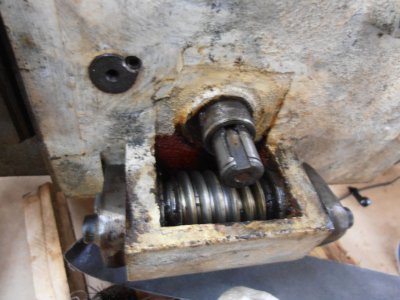
The shaft where the gear should have been was damaged. I noticed the gear shift for the carriage/cross feed was a little difficult to shift. This could have caused the damage if not disengaged in time causing a crash.
Has any other owners of the style seen damage like this? Am I correct in assuming that this damage is caused by hitting a shoulder or chuck when turning and should have been prevented by the ball detent clutch if adjusted properly?
Benny
The Orphanage Never Closes
Edited to correct manuals to 321350. Could not correct title stock number to same.
I need to get this lathe usable as soon as possible as I have promised my only operational lathe to a friend as soon as this one is up and going. It will probably take longer than I was planned because of the cold weather as I have no heat in the shop. I promised myself last winter that I would get heat installed before it got cold again but I did not keep that promise.
The dealer provided me with a hardcopy of the operator’s manual and a photocopy of the parts manual that matched the stock number on the machine tag. I have a little concern about the validity of these as they seem to show gray machines and the lathe I received is white but the “Stock No.” matched everything else looks okay. I checked the Jet tool website and they did not have these manuals available for download. I will try and convert these to PDF for anyone that may need one in the future. Meanwhile I am finding what appear to be errors in the manuals and will try to cover these issues as I work through this project.
The Jet numbers for these manuals are listed below:
Operator’s Manual Part No. M-321350 Dated 4/94
Parts List Part No. M-321350-1 Dated 4/94
Making use of the cold weather I have been spending some time looking at the web for information on this lathe and other import machines of similar design in order to get a sense of what is right and wrong with my lathe and manuals. I will try telling what little I have already found out so far about this “unplanned project” and try not to get long winded in the process.
The dealer was kind enough to let me tear into the lathe in his warehouse before I committed to the purchase. The first thing I noticed wrong was the cross feed did not work. The screw that connects the cross slide to the feed-screw nut was missing but I suspected more was wrong as there was a box of new and old parts on the skid beneath the lathe. That box contained a new feed screw and nut, a used feed screw/nut set and a mystery gear. I installed the new feed screw set along with the missing screw– problem fixed!
The dealer had his mechanic connect power to the lathe and we checked out the gears. The gear drive and all sounded and seemed ok except the carriage did not move. The mechanic quickly found that the output shaft from the gearbox was turning but the ball- detent overload clutch was not. He pulled the clutch back and found the balls were missing. This began to worry me!
I asked the dealer if I could inspect the carriage to see if there were more problems and he said OK. I removed the apron and found where the mystery gear fit.
The photo below is of the back side of the apron showing where the gear should be:

The shaft where the gear should have been was damaged. I noticed the gear shift for the carriage/cross feed was a little difficult to shift. This could have caused the damage if not disengaged in time causing a crash.
Has any other owners of the style seen damage like this? Am I correct in assuming that this damage is caused by hitting a shoulder or chuck when turning and should have been prevented by the ball detent clutch if adjusted properly?
Benny
The Orphanage Never Closes
Edited to correct manuals to 321350. Could not correct title stock number to same.
Last edited:

 Steve Shannon, P.E.