- Joined
- Nov 8, 2012
- Messages
- 2
I recently bought a 1973 J-head Bridgeport from a friend. I have submitted this post to tell the story of the refurbishment of this machine, mostly the head. Fortunately it all went pretty well but there are a few points that BP owners might find interesting.
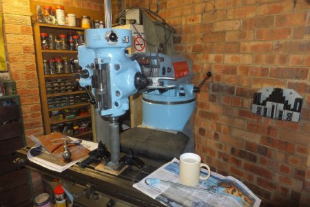
The machine appeared to be in very good condition and has had a reasonably easy life. The original scraping marks on the slides are still there so it has had little wear. The only external signs of age were sluggish handwheels, mainly on the table and a terrible paint job, with the paint peeling and flaking off. This was particularly bad on the head, ram and turret. So obviously a new paint job was in order at least. This meant dismantling the head.
Anyone completing this work must have “a Guide to Renovating the Bridgeport Series 1 “J” Head Milling Machine” by Ilion Industrial Services. This is an excellent manual and you can’t do the job properly without it.
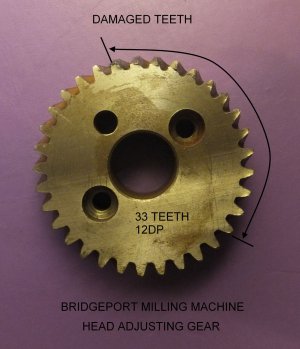
The first thing noticed was that the tiling gear was a wreck. It is a mystery how this could have been so badly damaged and the worm likewise had gouged and bent teeth. I can only guess that someone had loosened the head clamp screws too far so that the head displaced from the backing face such that the worm only contacted the teeth at the tips. This called for a new worm which I obtained from one of the suppliers that you can find on-line. I didn’t need to replace the tilting gear because I could re-install that rotated 180 degrees so that it presented unblemished teeth to the new worm. The damaged teeth will never see “action” again.
Now to the head: I dismantled this without any major hassles. Once the quill is out it’s not too heavy but in any event you have to be careful that you don’t let it drop on your fingers. It’s a good plan to have a large number of zip-lock plastic bags so that you can store parts according their grouping. I decided not to disassemble the spindle because it was in good condition; I had seen it run over a range of speeds before it came home and it looked OK.
Here are a few things that are worth telling that I observed during this exercise:
The pinion that engages with the rack on the rear of the quill was bone dry and a bit rusty. It looks as though it never gets any oil there. Does anyone have a solution to this?
After assembly I noticed that the quill was tight for about 1.5” of travel in the very top position. I called up the previous owner to see if I’d done anything wrong in re-assembly but he told me it had always been like that, particularly if it had been running at high speed for a long time and had heated up. I was a bit disappointed at this because I do a lot of fine work (clockmaking), besides it could be a nuisance and something that was just “not right’.
Then I noticed some text in the manual on page 72 concerning the quill nose-piece locking screw that reads: “Do not over tighten this set screw or it will force the quill to be out-of-round and the quill movement will bind near the top”. I’d vaguely remembered reading this before but because I wasn't planning to disassemble the quill I glossed over it. But immediately this set off a “Eureka” moment and guess what!? The screw was very tight. I A loosened this somewhat which greatly improved things.
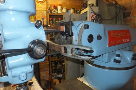
I made a support gadget to allow me to replace the head by myself. It was an easy fabrication (I sacrificed an R8 arbor that I'd never used). I got the idea from “Tubal Cain” who shows a similar support on his video on removing the head, but he doesn’t show you how to put it back. When you go to put the head back on there are 4 bolts to be aligned simultaneously and even with two people it would have been difficult to fit it back as you have to align the four tee-bolts manually and individually!!! They just kept falling to the bottom of the circular tee slot or misaligning and just wouldn't behave at all. Then I had an inspiration which you can see that on the photos. It was very simple to make up the two pieces of wood and it worked well and the bolts just slipped in like a dream. Note that the hole spacings are different on the top pair and bottom pair. I should point out again that the head with the quill is quite heavy, just about at the limit that I was "comfortable" with. This is without the backgear housing, etc. You should really get help to do this heavy lifting if you are planning to do most things by yourself, or better: use an engine hoist.
There’s a final problem with this machine that I have to deal with and I am not sure what to do yet; I am still thinking about it. The reason for the handwheels on the table not being as free as I’d like is that they have dual metric/imperial dials. These dials have two discs, one calibrated in mm and the other in inches with internal gearing (125T & 127T) and these give a lot of friction. The feed screws are imperial. I am leaning towards throwing the dial out and using imperial only as I’d prefer to have smooth operation rather than dual dials and if I ever get digital readouts they’ll be superfluous in any case. Does anyone else have experience with this?
I am converting this machine to 240V with a VFD and I’ll post an update on how I adapted the motor to fit the vee-belt housing in the near future.
Battiwallah


(Phil)


The machine appeared to be in very good condition and has had a reasonably easy life. The original scraping marks on the slides are still there so it has had little wear. The only external signs of age were sluggish handwheels, mainly on the table and a terrible paint job, with the paint peeling and flaking off. This was particularly bad on the head, ram and turret. So obviously a new paint job was in order at least. This meant dismantling the head.
Anyone completing this work must have “a Guide to Renovating the Bridgeport Series 1 “J” Head Milling Machine” by Ilion Industrial Services. This is an excellent manual and you can’t do the job properly without it.
The first thing noticed was that the tiling gear was a wreck. It is a mystery how this could have been so badly damaged and the worm likewise had gouged and bent teeth. I can only guess that someone had loosened the head clamp screws too far so that the head displaced from the backing face such that the worm only contacted the teeth at the tips. This called for a new worm which I obtained from one of the suppliers that you can find on-line. I didn’t need to replace the tilting gear because I could re-install that rotated 180 degrees so that it presented unblemished teeth to the new worm. The damaged teeth will never see “action” again.
Now to the head: I dismantled this without any major hassles. Once the quill is out it’s not too heavy but in any event you have to be careful that you don’t let it drop on your fingers. It’s a good plan to have a large number of zip-lock plastic bags so that you can store parts according their grouping. I decided not to disassemble the spindle because it was in good condition; I had seen it run over a range of speeds before it came home and it looked OK.
Here are a few things that are worth telling that I observed during this exercise:
The pinion that engages with the rack on the rear of the quill was bone dry and a bit rusty. It looks as though it never gets any oil there. Does anyone have a solution to this?
After assembly I noticed that the quill was tight for about 1.5” of travel in the very top position. I called up the previous owner to see if I’d done anything wrong in re-assembly but he told me it had always been like that, particularly if it had been running at high speed for a long time and had heated up. I was a bit disappointed at this because I do a lot of fine work (clockmaking), besides it could be a nuisance and something that was just “not right’.
Then I noticed some text in the manual on page 72 concerning the quill nose-piece locking screw that reads: “Do not over tighten this set screw or it will force the quill to be out-of-round and the quill movement will bind near the top”. I’d vaguely remembered reading this before but because I wasn't planning to disassemble the quill I glossed over it. But immediately this set off a “Eureka” moment and guess what!? The screw was very tight. I A loosened this somewhat which greatly improved things.
I made a support gadget to allow me to replace the head by myself. It was an easy fabrication (I sacrificed an R8 arbor that I'd never used). I got the idea from “Tubal Cain” who shows a similar support on his video on removing the head, but he doesn’t show you how to put it back. When you go to put the head back on there are 4 bolts to be aligned simultaneously and even with two people it would have been difficult to fit it back as you have to align the four tee-bolts manually and individually!!! They just kept falling to the bottom of the circular tee slot or misaligning and just wouldn't behave at all. Then I had an inspiration which you can see that on the photos. It was very simple to make up the two pieces of wood and it worked well and the bolts just slipped in like a dream. Note that the hole spacings are different on the top pair and bottom pair. I should point out again that the head with the quill is quite heavy, just about at the limit that I was "comfortable" with. This is without the backgear housing, etc. You should really get help to do this heavy lifting if you are planning to do most things by yourself, or better: use an engine hoist.
There’s a final problem with this machine that I have to deal with and I am not sure what to do yet; I am still thinking about it. The reason for the handwheels on the table not being as free as I’d like is that they have dual metric/imperial dials. These dials have two discs, one calibrated in mm and the other in inches with internal gearing (125T & 127T) and these give a lot of friction. The feed screws are imperial. I am leaning towards throwing the dial out and using imperial only as I’d prefer to have smooth operation rather than dual dials and if I ever get digital readouts they’ll be superfluous in any case. Does anyone else have experience with this?
I am converting this machine to 240V with a VFD and I’ll post an update on how I adapted the motor to fit the vee-belt housing in the near future.
Battiwallah


(Phil)


