[How do I?] Inherited Lathe Wiring

30coupestreet

Registered
Registered
Joined
May 25, 2024
Messages
4
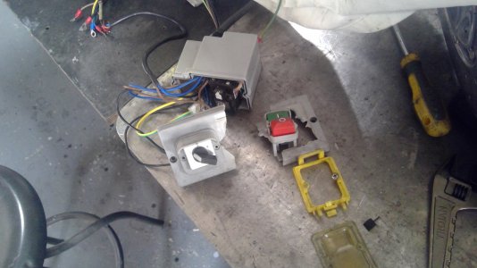
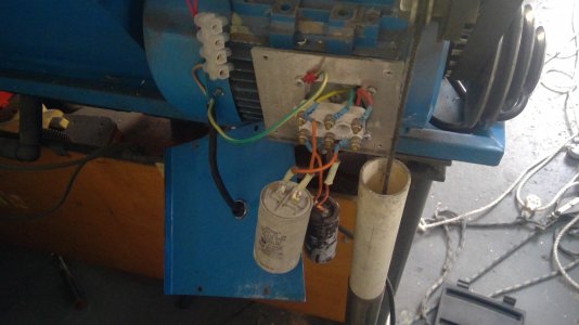
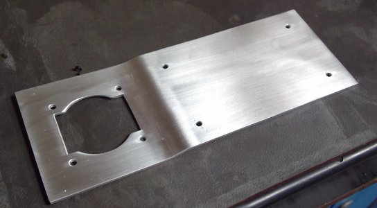
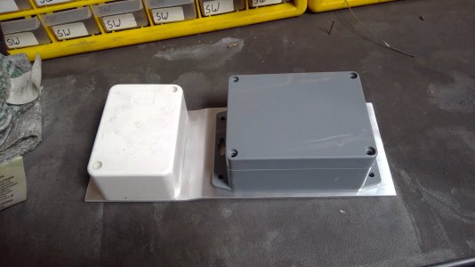
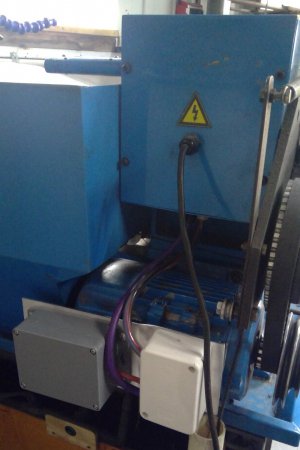
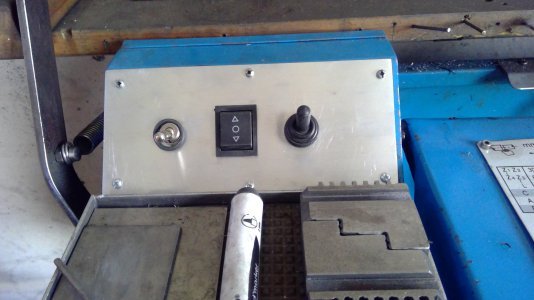
Looking for some wiring help with my bench top lathe I inherited from my Dad after he passed a way. Before he passed the drum switch stopped working. He got a new one but in his advanced age forgot to take pics or make notes on the wiring of the switch along with the main power on/off buttons and to the motor so when I pulled the lathe out of his shop it was all apart with no owners manual or wiring diagram. It's a typical Chinese lathe you find at a lot of the tool stores but there's no brand name etc so I am kinda shooting in the dark. Lathe is a 120v unit. Here are some pics of what I have. If there's a general wiring diagram for this set up as I am sure it's fairly common, please share.

IMG_3351.jpg
IMG_3343.jpg
IMG_3342.jpg
IMG_3341.jpg
 
Usually it's best to start at the motor first and id the wires/terminals
Get a photo or two of that and then we can dive in
Yes sorry I had a pic of the motor wiring as well, just forgot to post. Here it is. The second pic is the connections that go to the motor. I know the green ground wire of course.

lathemotor.png
IMG_3342.jpg
 
Is there any other motor data like a dataplate on it? If not we can still manage
Have a multitester/multimeter? Might need it


Anyhow, this is my best guess as to how it goes:
You might need to swap B and C and/or possibly one of the motor pairs
magsw1205p.jpeg
 
Last edited:
Got the wiring all done and thanks for the help gents. Had to fab a new mount for the switches as the drum switch is a bigger diameter than the original and the two wouldn't fit the old mount. Everything works like a charm! On another note, where can a guy get a replacement timing belt? this one is still good but is showing some cracks as it has dried out so don't think it has too much time left.

lathe.png
timingbelt.jpg
 
I had to rewire my lathe a while back when the on/off switch fell apart. Mine was 240volt with start and run capacitors. It had a rotary switch for forward reverse also. The Chinese in their wisdom, used the rotary switch to also connect the capacitors, impossible to follow.
I rang around trying to find a machinery electrician, but none would look at it without a wiring diagram, so I did the work myself.
I started by identifying the start and run coils in the motor, drew up a wiring diagram, replaced the latching switch with a simple toggle, replaced the rotary with a toggle also, installed a momentary on inching switch for threading, made a faceplate for the three switches and disconnected the chuck guard switch (PITA).
I also had to buy a box to contain the capacitors as the original had broken some time ago, bought a connection box and made a bracket to hold it all together.
Electric motor info can be found on the Web if you Google it. Quite an easy job, just a little time consuming..
 

Attachments

  • 123313139_3745509785494462_7970531889642092859_n.jpg
    123313139_3745509785494462_7970531889642092859_n.jpg
    346.8 KB · Views: 2
  • WIN_20201024_16_16_27_Pro.jpg
    WIN_20201024_16_16_27_Pro.jpg
    310.5 KB · Views: 2
  • WIN_20201031_11_41_24_Pro.jpg
    WIN_20201031_11_41_24_Pro.jpg
    462 KB · Views: 2
  • WIN_20201031_11_42_34_Pro (1).jpg
    WIN_20201031_11_42_34_Pro (1).jpg
    189.1 KB · Views: 1
  • WIN_20201031_16_40_22_Pro.jpg
    WIN_20201031_16_40_22_Pro.jpg
    158.2 KB · Views: 1
  • WIN_20240318_14_07_36_Pro.jpg
    WIN_20240318_14_07_36_Pro.jpg
    361.2 KB · Views: 2
Back
Top