IGaging DRO EMI Problem

kcoffield

Registered
Registered
Joined
Oct 2, 2020
Messages
175
I just finished a restoration of an old family lathe and added many upgrades. Among them was a three-phase motor with VFD and two iGaging Absolute DROs. The build thread is here.
I can be pretty handy with mechanical things but electronics is definitely not one of them…..as I’m sure I’m about to convince you. The following is a bit windy, but just trying to efficiently converge on a solution.

I used a small chain drag cable carrier for the DRO install to protect the cables. Here is a direct link to the DRO install portion of the thread.
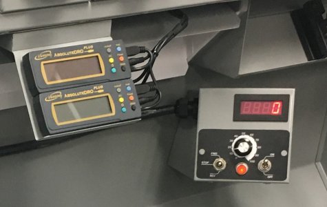
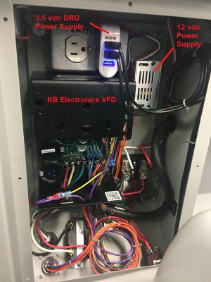
Unfortunately, that consumed most of the available DRO cable length, so I figured I’d just buy a couple cable extenders to remedy that. The DRO control cable connections are Micro USB, and the power ports are 3.5mm x 1.35mm barrel jacks and type A USB on the other end that plug into the power supply which is a cheap wall wart. I built a little panel to remotely mount the VFD controls and did same to mount the DRO displays. The VFD and some components are located in a built-in enclosure on the back splash. I also read the iGaging DROs are fond of eating batteries so I installed a cheap power supply and power cables. The DRO cables are routed through the electrical enclosure where the VFD resides and the added DRO power cables originate from there. Here’s a couple of pictures of the lay out.
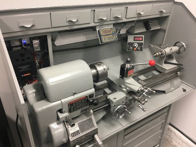
1 Lathe Layout.JPG
2 Elec Enclosure.JPG
3 Remote Controls Displays.jpg

I installed everything with the cable extensions routed as planned, powered up the DROs and they worked just fine……until I turned on the VFD. Then the DROs went crazy. The motor does not have to be running, just the VFD powered up. Upon a little investigation, I may have both a conducted and radiated emission problem.

There is still enough length of the factory iGaging control cables to reach the displays which can be moved and attached anywhere, but not routed in an acceptable manner. So suspecting the cable extensions weren’t adequately shielded, I eliminated the cable extensions…….and DROs still go bonkers when I power up the VFD. I disconnected the power cables and let the DROs revert to battery and problem solved. The extension cables are also routed on top of a 24” LED light which is another potential source of interference, but it doesn’t seem to matter whether that is on or off. I have not pulled the DRO extension cables out to see if rerouting these cables alone will solve the problem but I doubt it. I did have a couple other power cables so I pulled the power supply, plugged it into another 120vac circuit via extension cord, and with the power cables at least 3-4ft from the VFD, the displays still go off the charts when I attach the power supply, but are fine on battery.

So I’m looking for ideas to solve the problem. I sure would like to be able to use my present cable routing, but looking back, if one was trying to create an EMI problem, my scheme looks like a pretty sure way to do it.

I have read several other threads on iGaging noise susceptibility here on the forum, with a motor controller being the noise source. One was solved by a applying a capacitor across the power leads. I’ve inquired in that thread.

Since the factory control cables don’t seem to have a problem, do you think there is there any chance that I could just make a custom cable with good shielding, and the bypass cap across the power leads, and use the same cable routing? Or am I fighting a losing battle with proximity to the VFD?

A couple other tidbits, the iGaging absolute scales are stainless steel, and I believe they are grounded through mounting to the lathe, but I need to double check that because the lathe could be isolated by painted surfaces. All the metal surfaces on the cabinet, back splash, and lathe (tbc) are grounded. The 120 vac power source for everything is connected at a common node in the electrical enclosure….no filtering.

The small regulated 12 vdc power supply in the enclosure provides power for the tachometer. The tach has a magnetic sensor/pick-up located in the lower cabinet and its display and electronics are in the remote VFD panel. There are unshielded multiconductor 18 awg cables to the cabinet and remote panel routed through the electrical enclosure. The tach is completely unaffected and operates normally in all conditions. They are Amazon cheapies. I think the PS was $6 and the tach was $12.

The electrical enclosure looks pretty busy but it’s really only the VFD, and a couple small power supplies….the rest is just connectors and cabling.

Opinions/suggestions welcome.

Best,
Kelly
 
Last edited:
Revert to battery operation. I had these same readouts, maybe I replaced batteries every 6 months.
 
You can use shielded cable with a drain wire, or you can use ferrite beads. They work.

en-20120713-p1_img0001.png

images

71QT3AsfHpL.jpg
 
Some iGaging users have found that they needed to electrically isolate the scales from the machine. To do that it's necessary to make replacement mounting blocks out of plastic. You mentioned the fact that all the machine surfaces are painted, but the screw holes aren't, eh?

Having said that, I tried it on my mill and it didn't work for me. So try it on one axis first before spending more time on a potentially fruitless venture.

I put shield braid over the DRO cables: no improvement. As mentioned, insulated mounting blocks: no improvement. I put 1uf caps across Vcc and Gnd inside the read heads: that helped but did not eliminate the problem, at least not on my DROs with aluminum scales. However, I later got a pair of DROs for my lathe and they have stainless-steel rules -- and adding capacitors alone did the trick for them. So if I were you I'd just open up the read heads and solder in some capacitors across Vcc and Gnd. 1uF caps worked for me. And since there's only 3.3V there you don't have to worry about the voltage rating of the capacitors.

If you use electrolytics make sure the + side of the capacitors connect to Vcc. Also there's limited room inside the case so make sure what you get will fit inside. A 100uF capacitor probably won't (and is overkill anyway) :).
 
Thanks for the replies.

You can use shielded cable with a drain wire, or you can use ferrite beads. They work.
It'd be great if something as simple as the clip on ferrite bead would work. They're inexpensive. I see there a number of different materials for different frequency ranges. Any advice on that? I see those in Digikey.

How about high quality shielded USB cable? Micro B male to Micro B female seems hard to find except in the cheap consumer stuff. I need 5-6 ft of extension. I have braided sleeving I could pull over everything but Homebrewed didn't seem to have any success with it. I have not seen cabling other than the consumer stuff and there's a lot micro B extension cables that are just power cable and not all 5 pins active. Any recommended online sources for cables or ferrite cores?

1uF caps worked for me. And since there's only 3.3V there you don't have to worry about the voltage rating of the capacitors. If you use electrolytics make sure the + side of the capacitors connect to Vcc. Also there's limited room inside the case so make sure what you get will fit inside.
Could the cap be applied anywhere along the cable or must it be just prior to entering the board? ...or maybe in place of the battery? ...and are you thinking this could address both the power and communication cable?

Revert to battery operation. I had these same readouts, maybe I replaced batteries every 6 months.
It's an option.

Best,
Kelly
 
Some iGaging users have found that they needed to electrically isolate the scales from the machine. To do that it's necessary to make replacement mounting blocks out of plastic. You mentioned the fact that all the machine surfaces are painted, but the screw holes aren't, eh?

The four bolts that secure the lathe to the base aren't threaded into the cabinet or lathe, just through with nuts on the other side. I just need to get the meter and check. So are you saying isolating the gage may be worth a trying as well? It's not just the scale because the back of the sensor is connected with a metallic bracket as well.

Best,
Kelly
 
VFDs are switching high currents at kHz, These cause interference to any kind of lower level data signalling, such as the pulses from a DRO light sensor. There are very many ways the data can get jangled, and fully analyzing even one, all the way to the end, can take too long, and strain even big field theory brains. Fortunately, there are some basic steps to take that can reduce the interference by factors of thousands.

First to know about the pulses, and how they get jangled to make data errors, which software can find unacceptable, and quit altogether.
Most DROs is a fine glass grating scale, so fine it is hardly visible, but not all are that type. There are other technologies, but the LED light reflected sensor on glass scale is the most common. There are normally two scales, one displaced exactly halfway out of step with the other, The light reflection will produce ON/OFF states of light detection in the electronics, which then have to be sent to the measuring electronics as pulse voltages.
It is these voltages that can get contaminated by unwanted, often huge, noise voltages that leave them totally scrambled when it comes to detecting ON and OFF states.

How it can happen.
Signal voltages need to be shielded from external electromagnetic interference (EMI), and the ways this can happen are by what is known as "conducted", and another way called "radiated". The ferrite choke you see in the the picture in the previous posting is to choke currents on the outer of the shielding braid, so stopping the cable braid shield from becoming a huge and efficient antenna to switcher noise.

Digital pulse detection circuits, and sensor instrumentation , with their low voltages, are prone to getting messed up if they have a common ground, or zero volt point that is also a "ground" for high current switching circuits. Most commonly, the VFD has AC inputs, motor drive outputs, and an electronics control circuitry power and ground. DO NOT allow the 0V (GND) of the digital sensor power supply to casually share this connection. That is why for many, the "solution" is to use a separate battery DC supply. It keeps the currents apart. This unwanted bounce from sharing a return current route to 0V is called "common mode coupling.

Then there is magnetic coupling. The high frequency ON-OFF pulsing for motor currents generates magnetic fields, which will induce noise into any wires they couple to. Shielding wires in a braided shield will stop transmitted radio frequency fields, in both electric and magnetic, but not direct coupled close-up magnetic couplings.

Some basic things to do
Start with the VFD. There will normally be expansive and exact diagrams and connection explanation, Follow them to the letter. The switched wires to the motor terminals should be in a shielded cable intended for this stuff. If single phase, the wires should be spiral, such that any forward current is cancelled by its return current. The connection at the VFD outside the shield must be short, and not allow other wires to "link in" near the terminals. The shield must be bonded properly to the VFD shield connection terminal right there. The shielded route must be maintained all the way to the motor, and the shield connected to the motor frame. This "shield" is not to be confused with the motor AC safety earth wire, usually green/yellow striped.

The physical route of the motor must be kept well away from the sensors, not run parallel, nor laced up together with them. Berfore making the connections, it pays to put ferrite suppression chokes over the outside of the cables at two places. One in near the motor, Another is near the VFD. These suppression chokes need to be chosen for the purpose. They are bulkier than the little chokes seen on monitor leads. They need enough ferrite volume not to be driven into magnetic saturation by unwanted currents going around the motor drive wires. These things block huge interference from "transmitting" into the sensor wires.

The sensors
Simply routing the wires away from the possibility of what is called "near-field" coupling immediately cleans up the signals in an impressive way. The danger is if the cables for the sensors visit the same cabinet as the VFD, and have a non-isolated DC 5V supply in there, sharing a ground.
Internal to the sensor cables, one can ensure shielded twisted pair (interference-proof) conductors driven with a technology called "differential signalling" can be used. There are all sorts of technologies to get the pulses across, including resorting to fibre-optics.

For most folks, the cables from the sensors came ready-terminated with DB9 connectors, and they have to live with the wiring arrangements in the sensors unless they want to get up to some advanced noise reduction design. At the very least, I would expect the signals to be shielded twisted pairs, with every signal twisted with it's return, and the 0V not common and bonded to 0V GND ground. Even without peeping into the grounding and shielding of sensor cables, one can win. The only route left to bounce the signals around with switcher noise, is up the power supply wires. The simple expedient of using a power supply, isolated from the VFD currents, with a bit of a shield, and some braid over it grounded at one end only
can hugely clean up the signal. Putting inductive chokes in series, and one capacitor across the DC power leads can also make a difference.

But the screen over the wires "makes no difference".
That only means you have not found the coupling mechanism yet. If the basic precautions are used, nearly every system can be brought to the point the coupled noise is no longer a problem. Some VFDs are exceptionally rowdy, and need inductive + capacitive storage filter on the mains input to stop them distorting the mains waveform, and using the house wiring as a massive interference antenna. Agreed that EMC problems can be frustrating and intractable, but I assure you that however bad, once the route and type of coupling is identified, it can be put down, It is possible to return clean digital signals from sensors right inside motors as powerful as 110kW, which is the largest I ever personally dealt with.

When "adding a screen" can seem to make things worse, it is an indication the screen is being used as an antenna to help the coupling. Disconnecting one end of the screen, and using a couple of suppressors will bring that mechanism to a halt. Leaving both ends connected, but adding chokes can work. That is why the chokes are also called "braid breakers". They stop interference currents

If all else fails, then terminating the sensor leads with the correct resistive load, and using differential connected oscilloscope measurement, while checking out the VFD is the diagnostic route. Nobody should have to go that far. I only ever did it twice.

The hidden common mode earth.
The frame of the mill/lathe, whatever. A long route of ground safety earth wire, correctly doing its job as a safety earth, but coupling the father and mother of noise into the DRO power supply via the mains input connection. A input power low-pass filter to the VFD, having both common mode and differential filter components can block that. Even mounting the sensor on an insulating sheet, can defeat this route. In the end, imagine you are approaching the machine, VFD blazing away, and all the DRO kit in your arms, battery powered. If as you get closer, the DRO starts suffering, then the entire mechanism must be by radiated RF fields. There are almost zero situations where it can be so bad. Reasonable quality VFD's should have EMC filters internal. Adding a filter outside of it is a low cost fix.

I do accept that if you have not teased out how it is happening, it can be a right b**ch to solve. Do not expect there is just a single connection, or fix recipe. Even if it appears to "all come right", the noise margin may be very little.

"Quick fixes"
"Put a capacitor across it". That depends where. Never across the signals. Definitely across the power supply. having each lead (+) and (-) go through a 1mH inductor choke right at the powers supply terminals, and a capacitor 1uF to 10uF across the supply both before and after the choke can magnificently clean up the supply.

My apologies for the long posting. The subject has filled big books. I can't say you find a quick fix in any of this. I just know that installing with all this in mind should help avoid the worst.
 
Last edited:
I may have had a stroke of luck identifying the source of the problem.

I went out to the shop and figured I'd do some easy stuff for process of elimination. I powered everything up and to my surprise, everything is working fine with the VFD on and motor running at all speeds. What the heck? Then I noticed the 5vdc wall wart power supply laying by itself in the drip pan. I had not reinstalled it after my last test last night.

When I was testing the DRO power cables for being the possible source of interference, I was just disconnecting them at the DRO but leaving the other end of the cable plugged into the wall wart PS. Sure enough, when I plugged the wall wart and cables back in, it took the displays down even though the barrel jacks were not connected at the DRO end. If I run the DROs on battery and keep both ends of the DRO power cables disconnected everything is fine even with the DRO control cable extensions run through/near the VFD, they don't seem to be a problem.

The power cables are bundled and run side by side with the two Micro B USB extension cables that run to the DRO displays, so.......it appears the interference may be conducted through the wall wart PS into the DRO power cables and then radiated to the adjacent DRO control extension cables. I say conducted to/through the wall wart PS because if I plug the wall wart into a separate 120 vac circuit via extension cord, and use a loose cable to connect to the 5vdc to the DRO display, both completely away from the VFD, it still introduces the same interference and takes it down DRO displays.

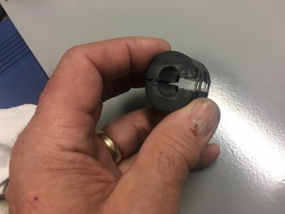
I did try snapping this ferrite core I had from an old audio power strip around the DRO power cables right where the exit the wall wart......no affect.

4 Ferrite Core.JPG

Maybe all I need is a real 5-6vdc power supply instead of the wall wart? or maybe just a filter on the ac power supply line to the wall wart? Hmmmm? What do you guys think?

I did check grounding. The lathe, cabinet, and backsplash are all earth grounded. So are the DRO magnetic scales. I can see continuity to ground by touching the exposed end of the cross slide scale and the grounding post in the electrical enclosure or any bare metal.

Best,
Kelly
 
Could the cap be applied anywhere along the cable or must it be just prior to entering the board? ...or maybe in place of the battery? ...and are you thinking this could address both the power and communication cable?

You will want the cap installed as close as possible to the noise-sensitive circuitry. If there's a significant length of cable between the cap and sensor, that will act like an antenna. With high speed noise, cables don't act like simple low-resistance connections so even a short length of cable could pretty much negate any benefit you might see from the capacitor.

For the same reason, you don't want to place the capacitor on the battery side of the cable. If the DRO design is similar to mine, the batteries are in the control/display box....on the wrong end of that long cable. You can't simply replace the batteries with a capacitor because when you plug the external power connector in, that disconnects the batteries.

Since my generation of DRO doesn't have the option for external power, I can't tell you if shielding the power cable will work or not. If you try it, you will need to connect the shield to the DRO ground. That's a bit problematic because its ground isn't brought out. A snap-on inductor might be the best solution for the power cable. Place it close to where the cable plugs into the DRO box.

iGaging DROs use capacitive sensing to track position so they inherently are more sensitive to electrical noise, compared to an optical or magnetic type of sensor. That's the price you pay for a lower-priced DRO.

I just saw your post regarding the wall-wart relationship to the problem. If it is a switcher-type supply those are reported to have poor isolation between the AC input and the DC output. A transformer-based power supply should reduce or eliminate that. You can get that type if you shop around. An isolation transformer would probably help if you want to keep your current power supply, but one of those will cost more than the right kind of wall-wart supply.
 
Last edited:
I just saw your post regarding the wall-wart relationship to the problem. If it is a switcher-type supply those are reported to have poor isolation between the AC input and the DC output. A transformer-based power supply should reduce or eliminate that. You can get that type if you shop around. An isolation transformer would probably help if you want to keep your current power supply, but one of those will cost more than the right kind of wall-wart supply.

I think we were posting at the same time. That's exactly what I was thinking. I'll have to root around and see if I have an older transformer style 5vdc supply.

One other curious thing, that receptacle in the electrical enclosure where the wall wart is plugged in is switched. For grins, I turned it off but left the wart and cables plugged in. It still created the DRO display interference even though it wasn't powered up, so maybe it is not purely conducted and that location to the VFD is vary high radiation, but, there was still interference even with the wall wart removed and plugged into another circuit. Also, if I just unplug the wart and leave it lay by the receptacle on top the VFD with the cables plugged in, there are no interference problems.

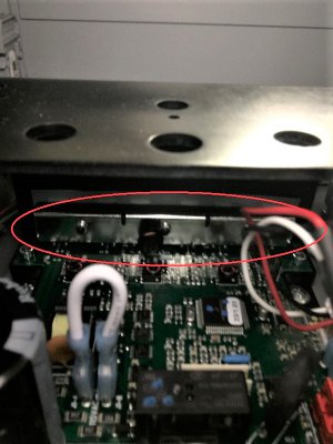
This is a picture looking up into the VFD. Those three devices circled are sinked to the wall immediately adjacent to that receptacle where the wall wart is plugged in. Any idea what they might be? Looks like a 3ph power switching device......solid state relays maybe?

5 VFD Components.JPG

I did quickly place that ferrite core at the DRO end of the cable. The display was still unstable but not quite a crazy without the core in place.

Thanks for the replies and help.

Best,
Kelly
 
Back
Top