I have a SB9x

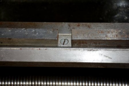
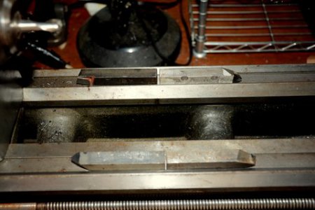
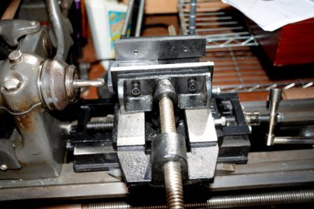
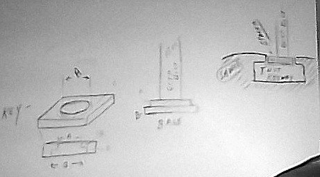
 48 C and I want to rig a end mill up to cut a bottom plate for the Shars AXA tool post I just bought. My plan is to place a cheap cross slide on the bed of the lathe and have the cross slide supported on the bed not the ways by setting it on some large cutting tools and then clamping it down using long bolts to the bottom of the bed with a cross plate. Since I will not have any thing on the ways I figure that should be OK but I am not sure the lateral torque when cutting will not send the cross slide off the cutting tools. I figure this is a hair brain plan but that is what I can do well. The cross slide is just sitting on the cutting tools in the pics, not bolted down. I just don't want to harm the lathe. Pics attached comments desired. Thanks


 48 C and I want to rig a end mill up to cut a bottom plate for the Shars AXA tool post I just bought. My plan is to place a cheap cross slide on the bed of the lathe and have the cross slide supported on the bed not the ways by setting it on some large cutting tools and then clamping it down using long bolts to the bottom of the bed with a cross plate. Since I will not have any thing on the ways I figure that should be OK but I am not sure the lateral torque when cutting will not send the cross slide off the cutting tools. I figure this is a hair brain plan but that is what I can do well. The cross slide is just sitting on the cutting tools in the pics, not bolted down. I just don't want to harm the lathe. Pics attached comments desired. Thanks
