- Joined
- Feb 2, 2013
- Messages
- 3,954
i Purchased a 3 axis IGaging EZ-View DRO kit,
it had a 24", 12" and 6" scales in the kit.
for my mill , it was going to be challenging to install the Y & Z axes without modifications
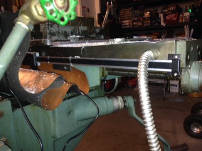
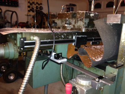
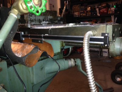
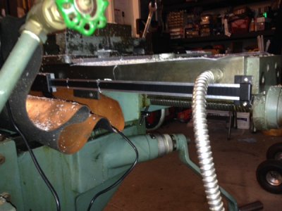
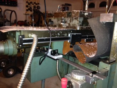
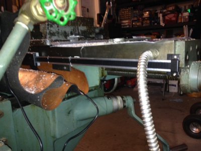
the X was relatively straightforward, but i decided to put it on the rear of the table- a little complication.
it just fit!
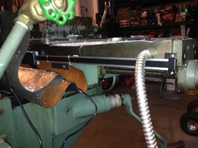
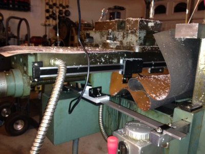
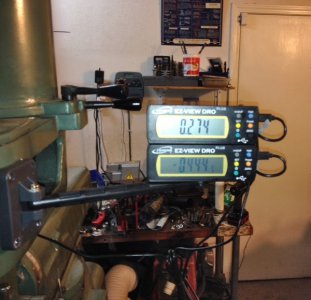
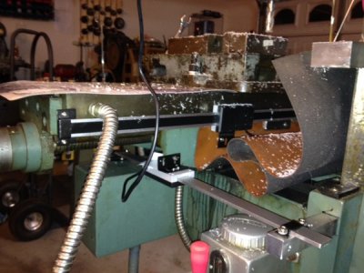
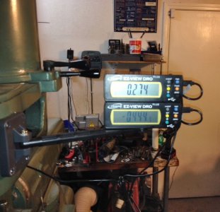
the Y an X are shown from the rear
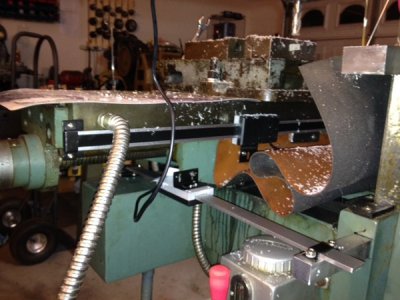
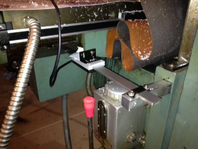
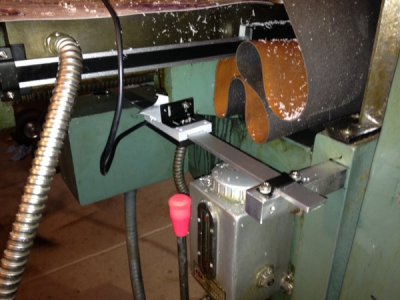
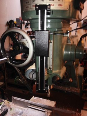
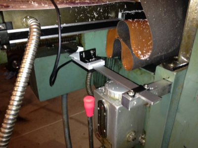
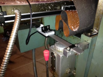
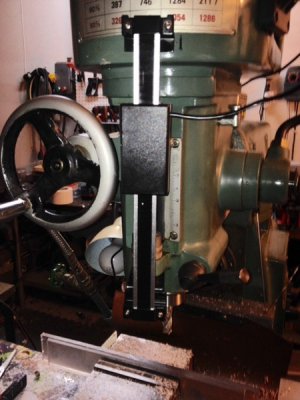
the Y from the front
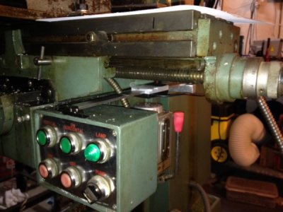
i needed to make a custom length stand off and drill a 1/4"-20 tpi stud into the knee casting
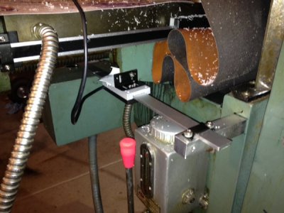
i messed up and drilled a hole into the main frame before realizing my mistake.
i recovered and drilled the standoff into the knee to travel with its motion
it looked sooo good in my head

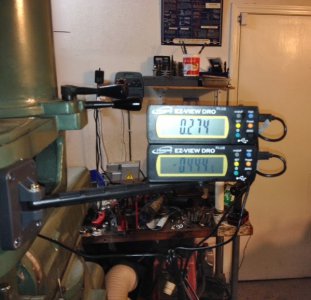
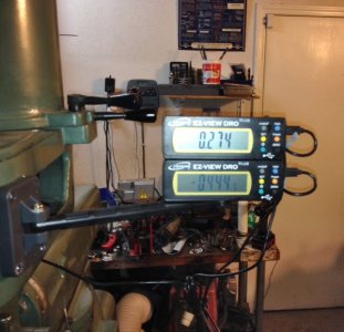
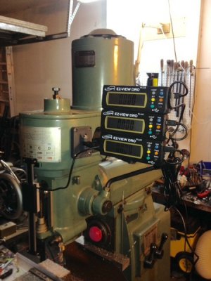
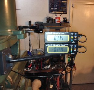
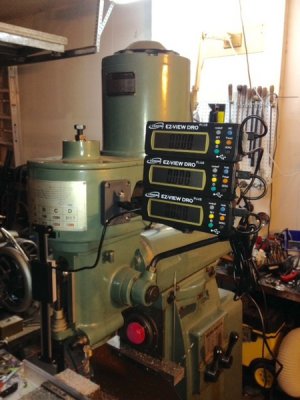
i mounted the X and Y displays and checked function !
the system worked so far!
here is the video!
now the tricky part: axis ZED
i contemplated modifying a small electronic claiper to use for the Z, then the gears in my head started turning.
the next thing i know i'm modifying parts from their installation kit to make it happen!
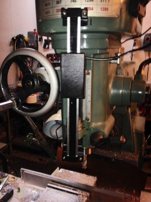
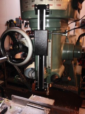
i drilled the upper housing and worked out the spacing for the lower half
i had to slightly cant the dro scale to avoid the quill downfeed wheel, but not interfere with the quill stop
it was kind of a PITA to do the Z, a lot of figuring, filing, spacing, & general tomfoolery before it worked without interfereing with the original operation of the quill stop and the quill depth stop
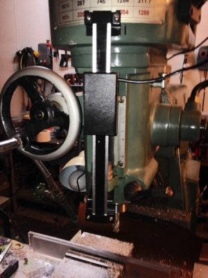
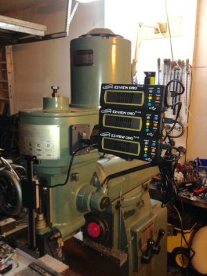
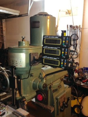
and then it was a simple to install the display on the stack.
and i gave the system a test!
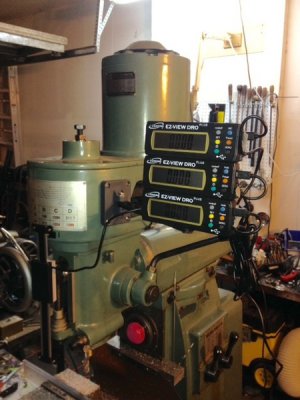
operation OK!
in the next segment, installing the dc converters to power the dro's without batteries!
thanks for looking and watching
it had a 24", 12" and 6" scales in the kit.
for my mill , it was going to be challenging to install the Y & Z axes without modifications
the X was relatively straightforward, but i decided to put it on the rear of the table- a little complication.
it just fit!

the Y an X are shown from the rear

the Y from the front

i needed to make a custom length stand off and drill a 1/4"-20 tpi stud into the knee casting

i messed up and drilled a hole into the main frame before realizing my mistake.
i recovered and drilled the standoff into the knee to travel with its motion
it looked sooo good in my head


i mounted the X and Y displays and checked function !
the system worked so far!
here is the video!
now the tricky part: axis ZED
i contemplated modifying a small electronic claiper to use for the Z, then the gears in my head started turning.
the next thing i know i'm modifying parts from their installation kit to make it happen!
i drilled the upper housing and worked out the spacing for the lower half
i had to slightly cant the dro scale to avoid the quill downfeed wheel, but not interfere with the quill stop
it was kind of a PITA to do the Z, a lot of figuring, filing, spacing, & general tomfoolery before it worked without interfereing with the original operation of the quill stop and the quill depth stop

and then it was a simple to install the display on the stack.
and i gave the system a test!

operation OK!
in the next segment, installing the dc converters to power the dro's without batteries!
thanks for looking and watching


Last edited:
