How would you go about machining this rough casting?

Lo-Fi

H-M Supporter - Silver Member
Joined
Dec 23, 2019
Messages
1,138
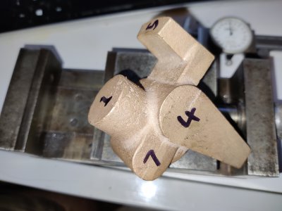
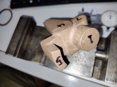
This thing is a swine:

2021-08-04 22.07.07.jpg2021-08-04 22.07.25.jpg2021-08-04 22.07.48.jpg

Print attached.

The part is gunmetal and rather "gummy". This is a replacement as the orignal had a massive void in it and I messed it up when my setup moved. It tilts on the M8 through hole and has a rotating fixture that sits on top running in the M14 hole. The curving bracket protruding to the side is simply for graduations, not a working surface. As mentioned on (my) drawing, it's critical that the through hole and vertical hole are perpendicular. The large 45 degree chamfer is a working surface and must be exactly conentric and true with the 14mm bore. Yes, the pointer makes it a collosal b****** to hold.

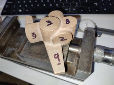
Just spitballing really. What would you attack with a file? How would you hold? What surface would you bring in first? Mill or lathe? How would you ensure alignment? Face plate, 4 jaw or fixture? Order of ops?.... Shoot! I thought numbering the various "flat and complanar (hahahaha)" surfaces would be helpful in discussion.

As far as relavant tools go, I have a Myford lathe, Bridgeport, rotary table and Wohlhaupter boring head available to me. Clamps, Kurt clone and the precision vise pictured that fits in the Kurt jaws can be taken as read.

If you're curious, it's a part from a Quorn tool and cutter grinder. I have pics and will do a write-up on the entire build in due course. It's proving to be huge fun!

Props to Hemmingway Kits for supplying the replacement part. I bought the kit from ebay years ago as an "it's crazy cheap, will build one day" buy and they were still happy to supply the part to me for a very reasonable price.

Thanks for reading!
 

Attachments

  • Tilting Bracket Drawing 1.pdf
    135.8 KB · Views: 45
I would make fixturing with blocks of wood, since there are so many curved surfaces
-Mark
 
Clamp part in vise and mill flat face 1 and 5. Take small cuts as this pass has the least support.
Flip the part over and then mill face 3, 8 and 9.
Clamp on faces 1 and 3 and 5, then mill faces 4 and 7.
Flip the part and again clamp on faces 1 and 3 and 5, then mill faces 2 and 6.

P.S. Only looked at your photos, not your drawing.
 
If you're curious, it's a part from a Quorn tool and cutter grinder.
Apologies if this sounds snarky, but have you tried following the suggestions in the booklet that accompanies the drawings from Hemingway?

They sufficed for me, though I don't remember exactly the sequence I followed.
 
I have the book by the good professor, but things have moved on since the 70s when the lathe was the only machine tool in the home shop. Some of the setups are truly diabolical! Other components could have taken days of faffing about, where the Bridgeport and boring head make accurate, quick work of it... This part, however... I can't help but think would have been better manufactured with the pointer as a separate part. The Hemingway drawings are tempting, but expensive, and also not for the version of the kit I've got, though I believe this particular part is unchanged. I've also adapted to work in metric.

Wooden fixtures sound interesting for initial work holding, and that's more or less the sequence I used the first time. It worked, then I believe a drill snagged in the void in the casting I didn't know was there and ripped the thing subtly out of alignment. I didn't realise until way later!
The most tricky feature is that 45 degree chamfer. It pretty much dictates being done in the lathe with the pointer heading towards the headstock and getting right in the way of any sane workholding. If it weren't for that, I'd do everything in the mill. As the part was junk anyway, I finish bored the 14mm hole, then made a tight fitting mandrel in the lathe to accept the part so I could run the chamfer. It wasn't as accurate as I'd like.

You guys have given me some ideas, though, so thank you! I'll report back. Still open to ideas, of course...
 
Check out Matty's Workshop on You Tube. He recently did a series on his Quorn grinder. I seem to remember him talking about figuring out the order of ops. He's got some other interesting projects on his channel. His channel is relatively new and doesn't have that many subs yet. I really enjoy watching him and Max Grant at the Swan Valley Machine Shop.
 
I still haven't finished mine (had to remake the spindle and OTHER STUFF seems to have put the project on the back burner) but it's very close to finished and I'd have struggled mightily without Hemingway's "Construction notes". I'm sure they'd sell them separately.

The instructions for that part have you first make the pivot bolt and collet on the lathe as well as a separate "pivot arbor" to use as a fixture during construction, leaving the compound at 20 degrees. (Okay, they call it a top slide, but it sounds funny when I write it!)

The pivot stub arbor has a 9/16" long stub threaded to M10 or 3/8" fine pitch, then a 40 degree taper for 1/4" followed by a 1/8" section at 5/8" diameter. The rest is whatever length and diameter you need to hold it in a collet (I used 0.500" diameter). Mill a couple of flats to use with a wrench, err ... spanner, on the end that goes in the collet.

You then layout and rough bore the pivot hole (marked 2 on your casting) in a 4-jaw chuck. They suggest using a scrap of steel (the photo shows a strap clamp) to span across the boss and stop face (1 and 5) to hold things securely in the chuck. Judicial filing by hand let me get everything held securely. Then drill and tap a hole for the pivot stub arbor I mentioned previously.

Next face the boss and index finger until they clean up. Then counterbore the hole to about 0.400" diameter by 0.300" deep. Then cut the 40-degree taper to the same depth. You can also turn the end of the finger to 2" diameter in this setup.

Next, insert and tighten the arbor, then flip it around and hold the arbor in a collet. Face the casting to 1 1/8" and finish the other 40-degree taper.

The next bit is done on the mill with the arbor held in a square collet block and the finger pointing up (you'll want a jack under the boss for support). Drill, bore and ream the spigot bore (1) to size (0.500"). If you are using split cotters, insert a tight-fitting sacrificial arbor in the spigot bore and hold it upright in the collet block, then bore and ream the cotter hole.

Then back to the lathe (I'll post another comment to continue).
 
Good heavens. I haven't touched mine in almost a year and it's SO CLOSE to finished!

 
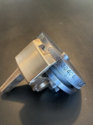
I bored some friends to death with emails as I proceeded through my build, but I can't find any on that part in particular. I did find a decent image of the final result out of the machine, though.

IMG_0438.jpg

Anyway, to continue with the Hemingway suggested order-of ops:

You next put a tight-fitting arbor in a collet on the lathe and clamp the part onto it using the split joint or double cotter (whatever you went with). Put the finger toward the tailstock. Use a boring bar to spot face the bottom of the boss to length to a diameter of 7/8".

Then reverse the casting on the arbor and face the other end of the boss (1" ) and the stop arm (1 1/8") to their correct heights above the pivot bore. Complete the 1/1/2" clearing cut.

Clean up the outside surface of the stop arm, and chamfer the top to 30 degrees and bottom (finger side) to 45 degrees.

Finally, set the compound to 45 degrees and bore the 90-degree taper 1/4" deep.

Leave the compound set and complete the actual spigot (the vertical part that holds the rotating work holding platform and has a taper to match what you put in the gunmetal part). These parts need to be machined accurately and mate well if you want the machine to perform well when you're done.

Back in the mill with a 0.500" arbor clamped in the spigot bore, you can machine the 3/8" wide by 30 degree slot in the tilting bracket.

Do NOT engrave the index marks until the entire machine is assembled and aligned.

Whew! Easier done than written (almost).
 
Back
Top