How to zero a radius turning tool on the lathe?

Paramax55

Registered
Registered
Joined
Aug 24, 2021
Messages
9
I just built a mount for my cheap, eBay radius tool today. I'm using it on an old Atlas lathe. This is a picture of my first attempt with the tool. It came out OK, but I was off by about .005 in the X axis. What I did was... I used a center in the tailstock to zero the cutter (by eye), then I pushed it up against the face of the material and zeroed the DRO. Then I loosened the cutter, swung it around to the Y axis, moved the X over the same distance as the radius, and pushed the cutter in to where it touched the side of the stock and tightened it back down. I figured this should have been my endpoint. Then I backed the cutter out in the y axis, fired up the lathe and started cutting. When I made my last pass, the Y axis was just right, but I was missing about .005 on the tip from the X axis. I moved it over and cleaned it up and it worked, but I don't consider .005 to be precision. Is there a better way to do what I was trying to do? Do I just need more practice?
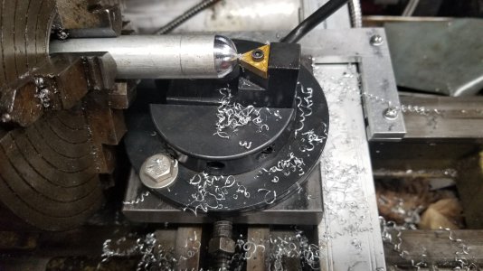
20210824_215738.jpg
 
The method described seems sound. I wonder if there is some play at the pivot that is causing this?
 
Ypu could make a tool that fits around the cylindrical part (maybe two points of contact) and holds a micrometer barrel (or a place to put calipers). Fiddle that so that you can set the micrometer to 1.00" at zero radius. Set it for some diameter, cut, measure, and then adjust zero on your tool. Great job for a 3D printer ;-)
I found pictures of the tool I use to pre-set my ball turner. Might help you...
c53789cea9a3859910f4b0520fa50f0c.jpg
7fc679e83c4bc03e54229b72cf5f7401.jpg


Sent from my SM-G892A using Tapatalk
 
I'm not entirely sure how your ball turning tool fits together, but it looks like the tool holder has rocked backward in the slotted base.
 
You know what? It DID rock backwards. Good eye! I'm not sure if it was when I adjusted it, or when I was using it.

I do like the idea of a "zeroing" indicator. I saw a video of a guy on youtube that chucked his in the 4-jaw, indicated it all up, then used the cutter to scribe a line across the tool holder and base.. Seems like it would be easy until it gets gunked up and scratched with chips and oil.

I need to make another piece and try it again. I may have done nothing wrong other than the fact that I didn't face off the piece before I started. It was faced from whatever project it was left over from and maybe it just wasn't true to the machine. I was tired and in a hurry (because, you know, quality...) and I just wanted to cut something with my new tool.
 
When I set my radius turner, I would rotate the turner to the rear after making a trial cut.. If the pivot point was too far to the rear, there would be clearance between the workpiece and the cutter. Too far to the front and the cutter would rub. When the pivot was aligned with a vertical plane through the spindle axis, the cutter would just touch the cut surface at the rear.
 
I ended up chucking it in the 4-jaw. I got it zeroed and scribed me some lines to use in the future. I think I can use the DRO to get the radius set from there. I'll cut some things and see how it goes.
 
I just built a mount for my cheap, eBay radius tool today. I'm using it on an old Atlas lathe. This is a picture of my first attempt with the tool. It came out OK, but I was off by about .005 in the X axis. What I did was... I used a center in the tailstock to zero the cutter (by eye), then I pushed it up against the face of the material and zeroed the DRO. Then I loosened the cutter, swung it around to the Y axis, moved the X over the same distance as the radius, and pushed the cutter in to where it touched the side of the stock and tightened it back down. I figured this should have been my endpoint. Then I backed the cutter out in the y axis, fired up the lathe and started cutting. When I made my last pass, the Y axis was just right, but I was missing about .005 on the tip from the X axis. I moved it over and cleaned it up and it worked, but I don't consider .005 to be precision. Is there a better way to do what I was trying to do? Do I just need more practice?
View attachment 376175
Two things you can do . First is lay a flat plate across top of ways on lathe. Then use a height gage to check centerline of lathe. If you turn a piece of stock to 1 inch dia then check top of turned dia and take half of that dia and you have true centerline . Then cut a 1 inch radius and check size . Once you have the 1 inch size take your whole radius tool to the mill and make a light cut across the back
of the adjustable cutting tool holder and the round base that holds the sliding tool . Now you know that when those two pieces of the radius tool are flat ,you have a one inch radius. Then if you slide the cutting tool in .100 your radius will be .200 smaller. Check how far you move the cutter in with a depth micrometer.
From then on you can set any dia by sliding the cutter in and out and you have constant starting point.
Jimsehr
One other way to check centerline is to chuck a piece of 1 inch stock in spindle and use that as a base to depth mic down to top of cutter. Once you mic down to .500 you know you are on center.
 
That doesn't sound far off from what I did. When I found center, I rotated the tool around to make sure I was on center - from the top and the bottom. I have a feeling that the error from my center scribe marks are going to be less than the couple thou error from not getting the tool aligned perfectly when I'm judging by scrape marks and such.
 
Back
Top