Mark,
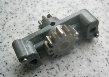
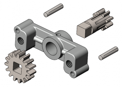
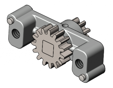
Press fit was my first thought, too, but on closer examination it looks like the large gear was joined to the pinion-and-shaft by swaging, which deforms material on one or both sides to lock two parts together, as in riveting. In this case it looks like the M6-68 pinion-and-shaft was swaged from the back side to lock the M6-102 gear to it after the pinion-and-shaft had been fed through the bore in the M6-11 gearcase. The shaft on the pinion can't be any larger than 0.375 or it wouldn't fit through the hole in the gearcase, so the squared off area at the end of the pinion shaft before swaging should be about 0.281", like that on the M6-38 half nut cam.
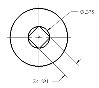
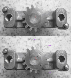
The square-ish area that looks like mashed material on the back side of the large gear is significantly larger than that at around 0.36".
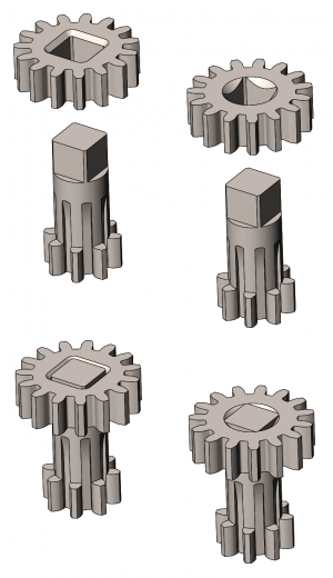
If this was done the back side of the swaged pinion and shaft would be deformed into a locking area on the back side of the of the 15-tooth gear. To keep the backside flush (no excess material protruding from the part surfaces) there would need to be somewhere for the swaged material to go. On a round hole it would usually be a chamfer, and that could work for this assembly, too, such as either of these:
My lathe was built around 1947 and, other than a rattle-can paint job, appears to be all original. I don't want to damage any part of it. If the parts are swaged together like it appears they are, I don't see any way this assembly can be taken apart without incurring damage. That is why I want to know if anyone has taken one of these assemblies apart.
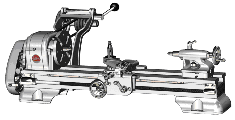
The reason why I want to take the assembly apart in the first place is because I am modeling the machine in CAD and creating drawings of all the parts and need more accurate measurements for these ones. I have completed about 3/4 of the drawings and am now working on the carriage.
