How To Do Lay Out For 8 Holes

Kroll

Active User
H-M Supporter Gold Member
Joined
Dec 23, 2012
Messages
1,307
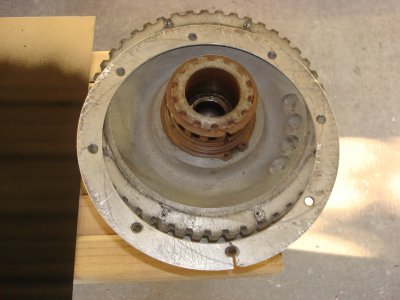
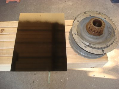
DSC02714.JPG Guys I need to try and figure out how to lay out 8-8/32 holes to match the SB mill gear.The other 1/16 thick plate mounts to the gear to keep the timing belt from sliding down has broke into and the old holes in the plate is wore out and very loose even when the screws are tight.I can figure out how to cut it into a circle but I am at a lost how to lay out for 8 holes that needs to match the gear.I have painted the plate so that I can see and try to do a good layout.
For me this is not an easy project cause I am not good at laying out holes(any kind of math) to match and I know that it will be hard for me to comprehend the best and easies answer but I am going to try.If you know of any websites that explains or and links to Youtubes,etc please let me know DSC02713.JPG
 
First, determine your bolt circle. If you have a digital caliper, use the inside measuring jaws to span one of the holes. Set the scale to "o" and then measure the distance between two directly opposite holes. Measure several combinations and average to get the best reading. Once you have determined the bolt circle diameter, mount your part to be machined and find its center. If you set your machine coordinates at o.o, then the four holes at N, S, E, & W are 0, +r; 0,-r; -r, 0; and +r, 0. The remaining four holes are at a 45 degree angle so the coordinates are +.7071r, +.7071r; +.7071r, -.7071r; -.7071r, -.7071r; &-.7071r,+.7071r.

This procedure can be done on any mill but is most easily done with a DRO equipped mill. Some DRO's have a bolt circle routine which automated this process. Another way to make the ring would be to use a rotary table which would simplify the process.

If you will be using a drill press to drill the holes and making the ring on the lathe, scribe the correct bolt circle diameter on the ring using a lathe tool. A pair of dividers can then be used to divide the circle into eight equal segments. Center punch and drill. Not as accurate as the previous methods but get you close enough.

Bob
 
One thing that I have done in the past (before I had a mill and DRO) and works well is to draw out the part in a CAD program, allowing it to space the 8 holes equally around the ring. Print out the drawing, lay it over and fasten it to the part, then punch the eight holes with either a prick punch or a center punch, then drill your holes. In your case using your mill is obviously out of the question. Do you have a drill press?
 
I have made parts like that with just a sabre saw, belt sander, drill press, sanding drum and transfer punches. I laid the old part on my material and traced the I.D. and O.D. Then after cutting closely with saber saw. I dykemed the inside and outside edges of the old part and clamped it to the newly cut piece. Using the belt sander I sanded the o.d. down til I just touched the dykem. Thus making the outside close to a true round. Did the same thing using a drum sander in a drill press. Then transfered the holes and drilled.
This works well if one does not have a cad program or a dro.
 
The OD and ID are easily found, just measure them from the old ring. The Bolt Circle is a tad different. You know the holes are 8-32. Use the gear, not the ring to determine the bolt Circle diameter. Put an 8-32 bolt in two of the holes 180 degrees apart or directly across from each other. Measure from outside to outside on these two bolts. Subtract the diameter of one bolt and you have the Bolt Circle Diameter. Old school but extremely accurate. The bolt locations are as stated in another post, an even 45 degrees apart on the Bolt Circle. It can be done faster than reading this post.

"Billy G"
 
Last edited by a moderator:
My standard way is to measure two opposite bolts. Measure the outside-to-outside and then inside-to-inside and average them.
-brino
 
All you need is outside to outside then subtract one bolt diameter. Why complicate it?? Try it your way by averaging then try mine. I'll bet the farm both answers are the same. You could even do it inside to inside and add one bolt diameter and the answer will still be the same. You are correct "brino" but it's a little more math. Thank you for adding that.

Pick your poison, all three ways are below. Let's use a bolt dia of .250

Your way "brino" ---- Outside is 6.250, Inside is 5.750, Average is 6.000. ( 6.250+5.750=12.000/2= 6.000)

My way ---- Outside is 6.250. Minus .250 = 6.000 (6.250-.250=6.000)

Third way Inside is 5.750. Plus .250 = 6.000 (5.750+.250=6)

All three ways are equal at 6.000 Bolt Circle Diameter. There are many was to skin the proverbial cat. I like simple ones.

"Billy G
 
Last edited by a moderator:
Quick way - turn the ring, fit transfer screws[1] in the pulley threads, clamp ring in correct centred position, tap over each transfer screw in turn - voila, eight hole locations prick-punched.

Slow way - measure over pairs of bolts, work out bolt-circle radius,
centre-punch centre of plate and set dividers to radius, scribe hole circle,
straight-edge and scriber, intersecting centre mark and hole circle, scribe first pair of hole locations; centrepunch 'em,
set dividers to 1-1/2 the radius, scribe arcs from the first pair which intersect at 90-degrees from the first pair - lay out scribed line through intersections and centre; centrepunch where the line intersects the bolt circle radius,
same again and again, splitting the 90-degree angles.

For threes and sixes, leave the dividers set to the radius and "walk" them around the circle, giving a mark every 60 degrees (pick alternate marks for three),

For twelve, mark out for six, then set the dividers slightly wider, bisect the 60-degree angles by laying lines from the centre to where the pairs of arcs intersect.

Old Skool, but it works as a last resort :)

Dave H. (the other one)

[1] Transfer screws:
take a bunch of high-tensile bolts and saw the heads off,
off to the bench grinder with remains (studs) and a cordless drill,
spin studs with drill and put a nice sharp point on 'em.
grind a pair of flats at the pointy end to grip while screwing in or out.

Screw in until just the point's proud of the surface (by 20-40 thou"), tapping the plate will put a nice neat punch=mark in the plate for each transfer-screw point.

This works really well of chuck-to-backplate drillings, lost covers for gearboxes etc. too!
 
Last edited by a moderator:
Yup, that's another way. Most hobby machinists don't have transfer screws though.

"Billy G"
 
Back
Top