- Joined
- Sep 22, 2010
- Messages
- 7,222
One man's way....
Centering Work in the Four Jaw Chuck - One Guy's Way
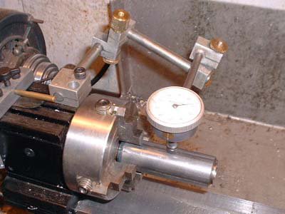
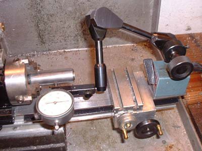
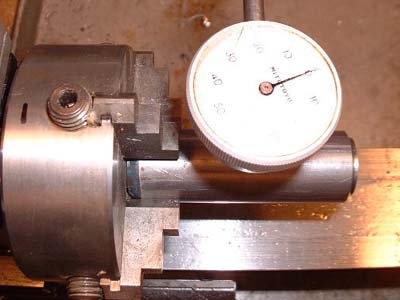
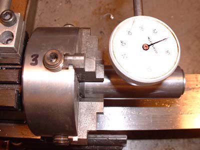
To easily center work in the 4J, you'll need to make yourself two tools. First, make a dedicated holder of some sort so you can mount a dial indicator (DI) on the tool post (or directly to the compound) with its axis perpendicular to the spindle axis. Adjust the DI so its plunger is vertically aligned with the spindle axis. An easy way to do this is to put a pointed tip on the DI plunger and align the point to a dead center in the headstock. The idea is to make something that you can drop into place, already aligned, and lock down in ten seconds or so. Leave the DI permanently mounted to this holder. A cheap import DI (<$15) is fine since we'll be using this only for comparative, not absolute, measurement.
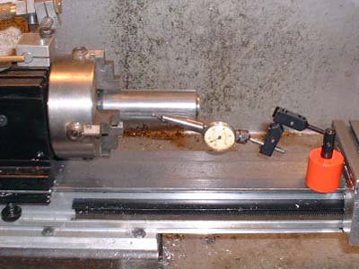
While you could use a conventional adjustable magnetic DI holder, I strongly recommend that you make a dedicated mount that is easily installed and removed. A general maxim of machining is that you'll be much more likely to do something 'the right way' if setting up to do it is quick and simple. If it isn't you're much more likely to try some half-a$$ed setup that doesn't work and ends up damaging the tool, the work, or, worst of all, you.
The second tool to make is a clone of your 4J chuck wrench. We're going to be adjusting two jaws at a time and it's infinitely easier to do if you can move both jaws in and out in concert without having to swap the wrench from hole to hole. It's another example of the maxim I mentioned above. The clone wrench doesn't have to be anything fancy. Machine a square tenon to match the existing wrench on the end of some suitable stock, and drill for a press-fit cross bar. Use your existing wrench as a guide for dimensions. I've found that, if there's not a lot of room on the back side of the lathe, making the clone somewhat shorter than the supplied wrench is a good idea.
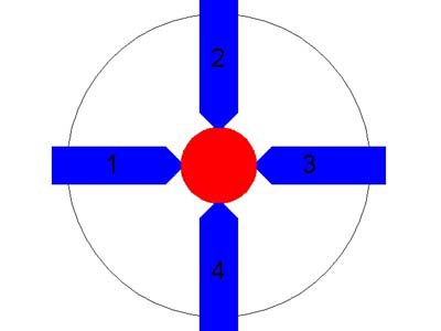
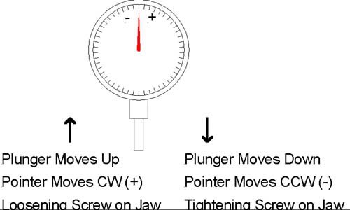
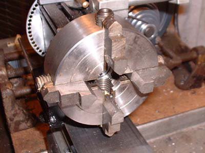
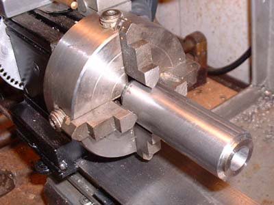
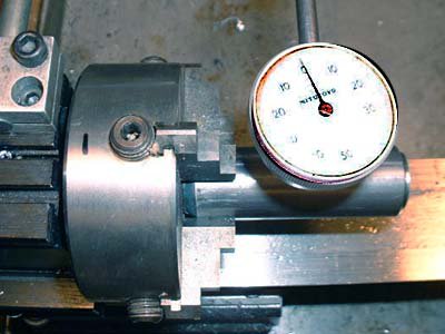
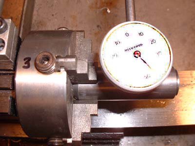
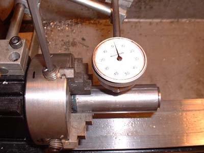
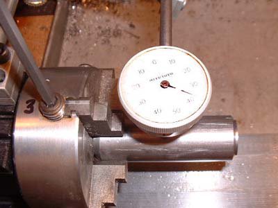
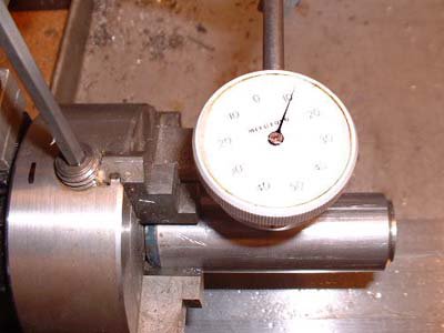
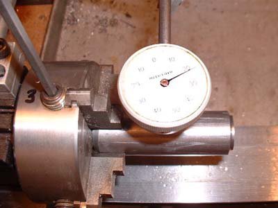
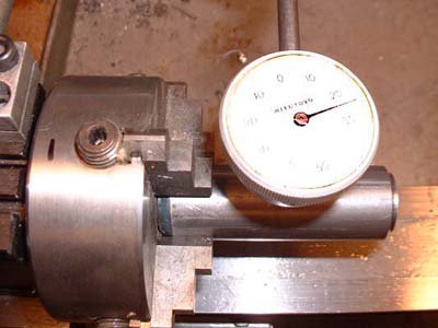
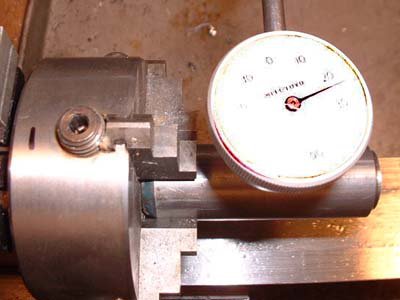
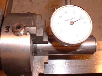
Ok, now for the procedure. Mount the work in the 4J and roughly center - either by eye or by using the concentric circles scribed into the face of most 4Js. Snug the jaws down so the work is held securely. Turn the chuck so one jaw is at the nine o'clock position as seen looking from the tailstock down the spindle axis. Use the cross-slide to bring the DI up against the work and reading about the middle of its range (e.g., about 0.5" on a 1" DI). Turn the scale on the DI so its needle indicates zero. Now swing the chuck through 180 degrees. Unless you've got an impossibly good eye, the DI will now read something other than zero. (For an example, let's say it reads 0.038.) Turn the DI scale so the zero is halfway to this reading. (Move the scale so the needle points to 0.019.)
Now, insert both chuck wrenches and adjust the jaws so the DI needle points to zero. Swing the chuck 180 degrees and check the reading - it should be close to zero.
[Aside: If the part you're centering has the same dimension in both jaw axes (i.e., it's not rectangular), the DI zero you established above will also be the zero for adjusting the other two jaws below - another advantage of this technique.]
Repeat this entire process for the two other jaws. [What we're doing here is treating the 4J as two two-jaw chucks. We can do this because the jaw pairs are orthogonal and, to first order, adjustments of one pair will have very little effect on the setting of the other pair.]
If you've been careful, the total runout on the part should now be only a few thou. Depending on your esthetics and the part requirements, this may be good enough. If not, repeat the entire process until the runout meets your needs. After centering, check to ensure that all the jaws are clamped down tightly. It's easy to leave one loose. If you have (left one loose), you may need to rerun the centering procedure after you've tightened it.
With this procedure, you should be able to center something to +/-0.001" in ten minutes on your first try. With not much practice, you can get that number down to one or two minutes. Soon your three-jaw will be gathering dust.
One of the most common uses of the 4J is for drilling/boring offset holes in eccentrics (i.e. cam drivers for model engines). In this case, you aren't centering the stock itself (as we were above) but rather need to center the location of the hole.
First centerdrill the location of the hole in the milling machine. Mount the stock in the 4J and roughly center this centerdrilled hole. [A fast way to do this is to use the pointy end of an edge finder held in the tailstock drill chuck.] Now you need a PUMP CENTER. This is a longish rod (mine is ~10" long). At the tailstock end is a spring-loaded female center. At the headstock end is a rigid male center. The male center goes in your centerdrilled hole. The female center is supported by a dead center in the tailstock and the tailstock is adjusted to lightly compress the spring. The DI is made to bear on the rod near the male center. Using the procedure outlined above, adjust the jaws until the DI shows little or no runout. Voila, the location of the offset hole is now centered.

