- Joined
- Feb 2, 2014
- Messages
- 1,217
This is from RogerL and others
First the disclaimer I am not a professional machinist I will show my methods of building a model engine. These are not necessarily the right way and surly not the only way to do it but my way.
These pictures are from several different model engine builds I have done and don't show all the operation.
Valves
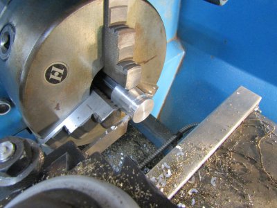
This shows turning a 5/16" valve using some 5/16" drill rod. Many of my engines have valves made from mystery steel or steel from the local hardware store. This may not be the best selection of materials especially if your completed engine doesn't get run very often or if you don't have a lubricant in the fuel mix to ward off rust. I use a 10 to 1 solution of Colman fuel to 1 part of WD40 in all my engines which is quite high considering that many two cycle engines run a 50 to1 ratio or more.
In this case I am shooting for a valve stem size that is around 0.125 in diameter and some longer in length than I think I will need. I am not concerned if the final size is 0.130 or 0.120 just that it has a nice finish and is consistent along the length. I will try to get close to my 0.125 by filing and sanding the stem but I am not anal about it.
The next operation is to cut the seat angle but remember never remove the part from the lathe between operations. The valve face and stem must be concentric to each other.
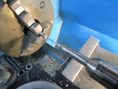
I move the tail post out of the way and set the compound slide to 45 degrees. When I first started making valves I would spend a lot of time trying to get exactly 45 degrees I even used a sine bar and shims to get as close as possible. I have since found a small deviation of degrees either side of 45 works just as well with a lot less hassle.
Using the same tool shown and using the compound slide I cut the face of the valve from the stem to the outer lip.
I touch up the face with a small fine file and sand paper.
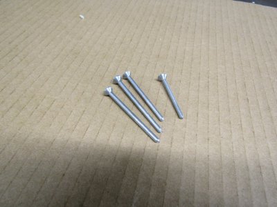
This shows 4 completed valves of varying lengths after the live center end was cut off and the face end ground smooth.
Valve seats
Valve seats are made from 5/16" brass and again all operations are preformed except the last one with out the removal of the stock.
I start by measuring and finding the smallest diameter of my valve stems and drill the appropriate size center hole deeper into the brass than I will need. Next I use a 0.200 drill to bore in a distance past where the intake and exhaust ports will intersect the guides when installed in the head.
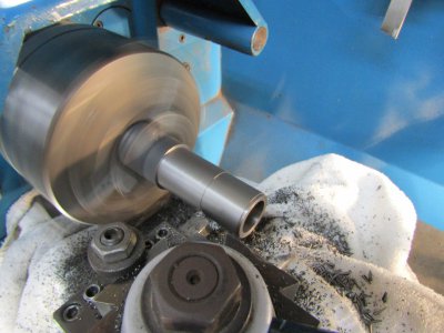
The picture shows 5/8 brass rod that I have turned down to 5/16".
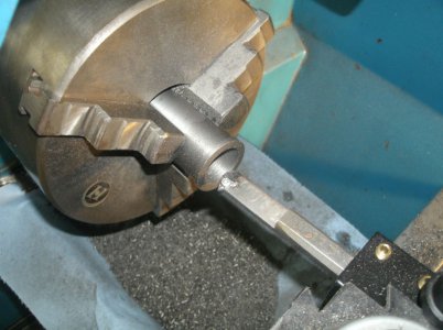
Here is a very expensive and precise 45 degree deburring tool (one of a cheap set from China) is mounted in the tail post for cutting the guide face.
Cut it deep enough to raise a small burr on the end of the brass guide then use a file to smooth over and clean up the end.
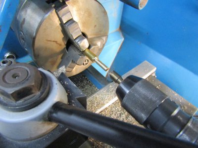
Part off the guide, flip it around and make a step for the valve spring to set on.
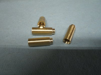
The valve guide should have a light press into the cylinder head with some Loctite added for good measure but only apply pressure to the valve spring end not the guide's face. The valve seat end of the guide is very thin and easily damaged. Don't get too hung up here if the guide is just a finger press or even some looser as Loctite is your friend.
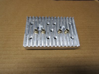
When the Loctite has cured drill the intersecting holes in the head for the intake and exhaust ports into the valve guides.
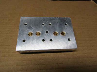
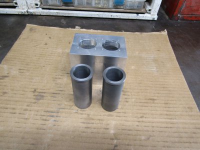
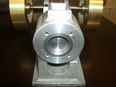
Theses pictures show the head from my Two Timer build.
Lapping in the valves
Test fit the valves into the valve guides and choose the best fit for each. Each valve with it's the chosen guide will from now on be married together.
With the cylinder head in hand and a short piece of rubber hose stuck on the valve stem a small amount of valve grinding compound is applied to the valve face.
With a little pull and a back and forth rotating motion, the hose is spun between your fingers for about 50 cycles. Stop and turn the valve about a quarter of a turn and repeat this sequence at least 4 times. Remove the valve and clean all the surfaces of grinding compound. Valve grinding compound is quite course but as it is worked it gets broken down into finer and finer particles but not fine enough.
I now apply a coating of a copper cleaner paste to the valve face and complete the above process again. I understand that tooth paste works just as well but I never have tried it. I did try using an electric drill to spin the valves instead of twisting them by hand but I find I still have to revert back to this process to get a good seal.
The next step requires making a test plate that has an air fitting on the back and the cylinder head bolted to the front. A recess has been milled in the front of the plate to allow for movement the valves. Attach an air hose with about 60 lbs pressure and cycle the valves to clear them of any debris. Any leaks will be easy to hear and find as you rotate and cycle the valves. If you are really into perfection you can dunk this whole assembly into a bucket of water and any leaks are quite easy to see. Remove the head and do some more lapping with the copper paste and recheck. I have found that a reasonable amount of care and sealing is fine and 100% is not necessary. I have also found that valves tend seat in some after running the engine and usually get better with age.
I have tried in the past to just skip making a test plate and install the heads after lapping. I usually end up making a test plate anyway after disassembling the engine.
This picture is from one of my single cylinder builds.
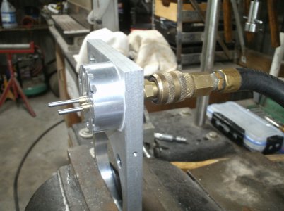
At this stage you know how well your valves will seal so if you have a low compression problem it is probably somewhere else.
Hope this helps
Thanks for looking
Ray
I was wondering if you could do a build tread on just how you make the piston, ring, and cylinder liner. Go over in detail on the process you use to make all the critical parts, Surface finishes, lapping, etc. The theories you use for the design. Also do the same thing for the valves and valve seats. What valve seat angle do you use, how do you cut the valves and valve seats. How do you lap the valves? How do you test to see the valves are sealing properly. I know that I could learn a great deal from your experience on these two key areas.
First the disclaimer I am not a professional machinist I will show my methods of building a model engine. These are not necessarily the right way and surly not the only way to do it but my way.
These pictures are from several different model engine builds I have done and don't show all the operation.
Valves
This shows turning a 5/16" valve using some 5/16" drill rod. Many of my engines have valves made from mystery steel or steel from the local hardware store. This may not be the best selection of materials especially if your completed engine doesn't get run very often or if you don't have a lubricant in the fuel mix to ward off rust. I use a 10 to 1 solution of Colman fuel to 1 part of WD40 in all my engines which is quite high considering that many two cycle engines run a 50 to1 ratio or more.
In this case I am shooting for a valve stem size that is around 0.125 in diameter and some longer in length than I think I will need. I am not concerned if the final size is 0.130 or 0.120 just that it has a nice finish and is consistent along the length. I will try to get close to my 0.125 by filing and sanding the stem but I am not anal about it.
The next operation is to cut the seat angle but remember never remove the part from the lathe between operations. The valve face and stem must be concentric to each other.
I move the tail post out of the way and set the compound slide to 45 degrees. When I first started making valves I would spend a lot of time trying to get exactly 45 degrees I even used a sine bar and shims to get as close as possible. I have since found a small deviation of degrees either side of 45 works just as well with a lot less hassle.
Using the same tool shown and using the compound slide I cut the face of the valve from the stem to the outer lip.
I touch up the face with a small fine file and sand paper.

This shows 4 completed valves of varying lengths after the live center end was cut off and the face end ground smooth.

Valve seats
Valve seats are made from 5/16" brass and again all operations are preformed except the last one with out the removal of the stock.
I start by measuring and finding the smallest diameter of my valve stems and drill the appropriate size center hole deeper into the brass than I will need. Next I use a 0.200 drill to bore in a distance past where the intake and exhaust ports will intersect the guides when installed in the head.
The picture shows 5/8 brass rod that I have turned down to 5/16".
Here is a very expensive and precise 45 degree deburring tool (one of a cheap set from China) is mounted in the tail post for cutting the guide face.
Cut it deep enough to raise a small burr on the end of the brass guide then use a file to smooth over and clean up the end.

Part off the guide, flip it around and make a step for the valve spring to set on.

The valve guide should have a light press into the cylinder head with some Loctite added for good measure but only apply pressure to the valve spring end not the guide's face. The valve seat end of the guide is very thin and easily damaged. Don't get too hung up here if the guide is just a finger press or even some looser as Loctite is your friend.
When the Loctite has cured drill the intersecting holes in the head for the intake and exhaust ports into the valve guides.

Theses pictures show the head from my Two Timer build.

Lapping in the valves
Test fit the valves into the valve guides and choose the best fit for each. Each valve with it's the chosen guide will from now on be married together.
With the cylinder head in hand and a short piece of rubber hose stuck on the valve stem a small amount of valve grinding compound is applied to the valve face.
With a little pull and a back and forth rotating motion, the hose is spun between your fingers for about 50 cycles. Stop and turn the valve about a quarter of a turn and repeat this sequence at least 4 times. Remove the valve and clean all the surfaces of grinding compound. Valve grinding compound is quite course but as it is worked it gets broken down into finer and finer particles but not fine enough.
I now apply a coating of a copper cleaner paste to the valve face and complete the above process again. I understand that tooth paste works just as well but I never have tried it. I did try using an electric drill to spin the valves instead of twisting them by hand but I find I still have to revert back to this process to get a good seal.
The next step requires making a test plate that has an air fitting on the back and the cylinder head bolted to the front. A recess has been milled in the front of the plate to allow for movement the valves. Attach an air hose with about 60 lbs pressure and cycle the valves to clear them of any debris. Any leaks will be easy to hear and find as you rotate and cycle the valves. If you are really into perfection you can dunk this whole assembly into a bucket of water and any leaks are quite easy to see. Remove the head and do some more lapping with the copper paste and recheck. I have found that a reasonable amount of care and sealing is fine and 100% is not necessary. I have also found that valves tend seat in some after running the engine and usually get better with age.
I have tried in the past to just skip making a test plate and install the heads after lapping. I usually end up making a test plate anyway after disassembling the engine.
This picture is from one of my single cylinder builds.

At this stage you know how well your valves will seal so if you have a low compression problem it is probably somewhere else.
Hope this helps
Thanks for looking
Ray

