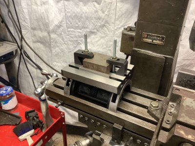
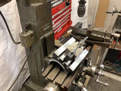
I have a sine plate so the procedure is somewhat different. To properly use a sine plate or an angle plate, it is necessary sweep the rotational axis or a proxy of it. In my case, I can access the pivot pin with a test indicator. In the case of an angle plate, the rotational axis is virtual so it would seem that a certain amount of trust in the manufacturer's machining accuracy is necessary. If you are comfortable that the edges of the table are square and parallel to the rotational axis, you can use one of the two parallel edges of the table as the proxy. With the table set horizontal , sweep one of the parallel edges to set up the plate and lock the base in place. To set an accurate angle on the plate, You can set the z distance to the plate ising a dial indicator and move the table a a set displacement in direction perpendicular to the rotational axis. Then adjust the z axis to rezero the dial indicator or if, enough travel on the indicator, note its new reading. The angle can be calculated from the arctan of the ratio of the z axis displacement and the table displacement.
The workpiece can be mounted prior or after setup of the angle plate, depending on its geometry. You will most likely want to orient some feature with respect to the rotational axis. As an example, if you were making a V block, you would want the cut for the V to be parallel to one edge and you would probably set the edge prior to adjusting the plate angle.
There are a lot of factors that make an angle plate accurate. The base and the top plate must be machined parallel to the rotational axis. The edges of the top plate should be square to the rotational axis and square to the top surface of the plate.
As an initial trust but verify operation to qualify the angle plate prior to use, I would set the angle plate for horizontal and one edge parallel to a mill axis Then, I would sweep the top surface and adjust the plate so the surface was horizontal. If I couldn't get a sweep in the direction of the rotational axis to to zero, ot would indicate a manufacturing defect which could be corrected by grinding the top surface. Next, I would sweep the remaining three edges to determine squareness of the plate. To check if the top plate was parallel to the rotational axis to the rotational axis, I would tilt the plate to on extreme and sweep one of the parallel edges. with an edge finder. Then I would rotate the plate to the other extreme and repeat. Assuming that all sweeps are satisfactory, I would feel confident using one of the edges as a proxy for the rotational axis in my future fixture setups.


