- Joined
- Mar 2, 2018
- Messages
- 232
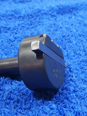
I'm going to make wheels for a clock soon, so I turned my attention to how I was going to hold the tool, and what kind of tool I was going to use. Some guys use round stock turned on a lathe. It's easy to get a symmetrical profile on both cutting edges, but you take a lot of meat off the tool, and it's harder to align a round tool. I decided to go with a square tool that's way oversized for the tooth profile I'm going to cut, and I made a big, heavy holder for it. The disadvantage of going so big is the tool will take a long time to go around for another swipe at the part, but I'm hoping the extra mass compared to most designs I've seen will make for a smoother cutting tool. I haven't ground the tool bit yet, so I haven't tested this. I did spin it up to 2400 RPM in the lathe, and I have all my teeth. Well, all but one of my teeth, but that's an unrelated story. 
I started with some rusty 2" steel in the 3-jaw:
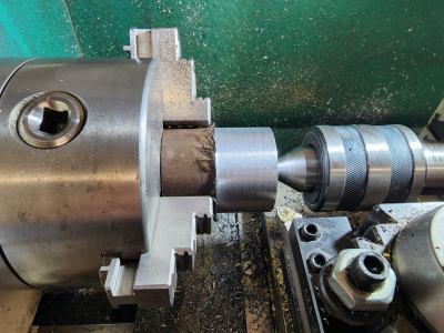
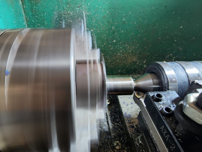
I was shooting for 0.750" on the shank, but I mess up the math somewhere and took too much off, so I moved down to 11/16".
It was at this point that I gave up on my rotary table chuck. I indicated the top of the part, and it was way off. I indicated the top of the chuck, and it was also way off. Bad mounting plate, bad mount, not sure. I ditched it all for an ER32 collet holder, but here the part was in the chuck:
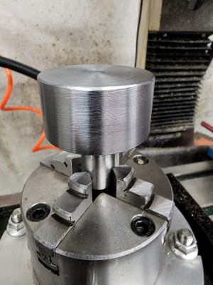
I used my new DRO to get back to the center of the rotary table a couple weeks since the last time I used it. Then I indicated the OD of the part. It was off by about 0.005" so I indicated the collet holder, which was only off by about 0.0005". I'd say the 0 point was still the 0 point! It's good to know I can trust my DRO. So then I calculated where to move the Y axis so the edge that would present the cutter would be exactly on the centerline. Not pictured, I proceeded to completely screw up the part, because I didn't lock the rotary table down. Genius! I'm a genius! So I took it to the lathe and trimmed off about 1/4".
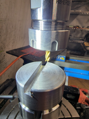
For once I did something right. I moved back 0.020" and made another pass. I was aiming for about a piece of paper slop in the slot, to be tightened up with set screws, and I got it.
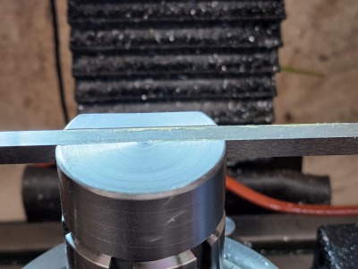
I mounted the part in a 5C collet block, which reminded me why 5C collet blocks suck. If I had ER collet blocks, I could make all the adjustments on the outside of the vise jaws.
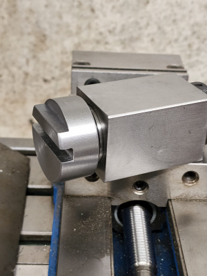
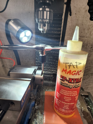
As BlondieHacks says, "Tappy tap tap." I ran the taps in with the spindle set at the lowest possible speed, then hand tapped to finish.
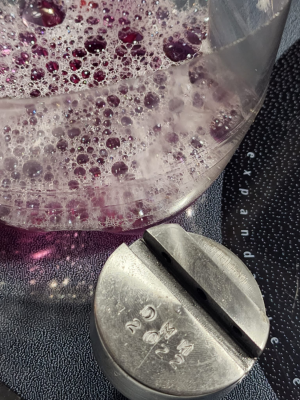
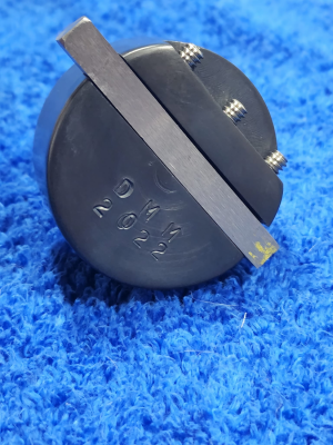
I took the time to stamp my initials and the date. I also hand filed all the sharp edges. This one's going to be a keeper. Even if it doesn't work out for cutting wheels, it will be useful for something. First a dunk in Purple Power.
Next, acetone, which I lit on fire to burn off the residue while heating the part for a dunk in Van's gun blue. I used stainless steel set screws because I wanted this thing to be pretty. Et voilà:
I started with some rusty 2" steel in the 3-jaw:

I was shooting for 0.750" on the shank, but I mess up the math somewhere and took too much off, so I moved down to 11/16".

It was at this point that I gave up on my rotary table chuck. I indicated the top of the part, and it was way off. I indicated the top of the chuck, and it was also way off. Bad mounting plate, bad mount, not sure. I ditched it all for an ER32 collet holder, but here the part was in the chuck:

I used my new DRO to get back to the center of the rotary table a couple weeks since the last time I used it. Then I indicated the OD of the part. It was off by about 0.005" so I indicated the collet holder, which was only off by about 0.0005". I'd say the 0 point was still the 0 point! It's good to know I can trust my DRO. So then I calculated where to move the Y axis so the edge that would present the cutter would be exactly on the centerline. Not pictured, I proceeded to completely screw up the part, because I didn't lock the rotary table down. Genius! I'm a genius! So I took it to the lathe and trimmed off about 1/4".

For once I did something right. I moved back 0.020" and made another pass. I was aiming for about a piece of paper slop in the slot, to be tightened up with set screws, and I got it.

I mounted the part in a 5C collet block, which reminded me why 5C collet blocks suck. If I had ER collet blocks, I could make all the adjustments on the outside of the vise jaws.

As BlondieHacks says, "Tappy tap tap." I ran the taps in with the spindle set at the lowest possible speed, then hand tapped to finish.

I took the time to stamp my initials and the date. I also hand filed all the sharp edges. This one's going to be a keeper. Even if it doesn't work out for cutting wheels, it will be useful for something. First a dunk in Purple Power.

Next, acetone, which I lit on fire to burn off the residue while heating the part for a dunk in Van's gun blue. I used stainless steel set screws because I wanted this thing to be pretty. Et voilà:


