-
Welcome back Guest! Did you know you can mentor other members here at H-M? If not, please check out our Relaunch of Hobby Machinist Mentoring Program!
You are using an out of date browser. It may not display this or other websites correctly.
You should upgrade or use an alternative browser.
You should upgrade or use an alternative browser.
Help with the spindle speed diagram.
- Thread starter mgyB
- Start date
- Joined
- Apr 17, 2015
- Messages
- 323
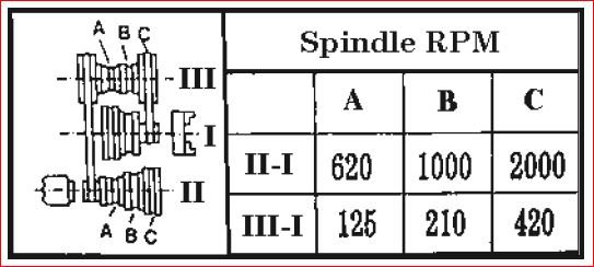
Looks like Joe P has it correct; I= spindle, II= Motor, and III= Idler. The layout of the drawing is confusing so I would not feel bad about not understanding it. To be honest I cant see enough on the machine to be sure what I tell you is correct. Can you tell me what the make and model of the lathe is and Id be happy to take a look for more information for you. I just don't want to tell you something wrong
- Joined
- Apr 30, 2015
- Messages
- 12,251
Not surprised you don't get it- the pictorial is a rolling disaster- if you look close you can see a picture of a chuck on I
For the three highest speeds, the idler is bypassed and the spindle belt goes directly to the motor. The orientation of the various pulley flange groups is drawn backwards compared to the actual machine
Mark
For the three highest speeds, the idler is bypassed and the spindle belt goes directly to the motor. The orientation of the various pulley flange groups is drawn backwards compared to the actual machine
Mark
Last edited:
- Joined
- Sep 15, 2017
- Messages
- 321
To me it appears the way its set now would be the slowest speed and you would shift the belt step by step towards the lathe to increase speed for first three speeds
Then to select the next 3 speeds you would need to reverse the motor pulley and idler pulley to select next three speeds moving the belt step by step away from lathe to increase speed .
At least thats what i think i can make of it hope this helps a bit.
Sorry looking again that does not seem right in what ive said .
Last edited:
- Joined
- Apr 17, 2015
- Messages
- 323
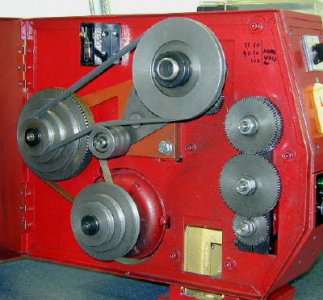
That is what I was trying to tell, but in the photo I can not see if there are smaller stepped pulleys behind the large one on the spindle. They are kind of drawn on what they pass off as a diagram with the cryptic chuck and motor on it
- Joined
- Apr 30, 2015
- Messages
- 12,251
Yes the spindle pulley has 3 steps, so for the highest 3 speeds the idler/countershaft is bypassed and the belt goes from motor to spindle
You wouldn't know it though from the crazy way they drew it- 5 demerits for that person
You wouldn't know it though from the crazy way they drew it- 5 demerits for that person
Last edited:
- Joined
- Jul 8, 2018
- Messages
- 880
That is what I was trying to tell, but in the photo I can not see if there are smaller stepped pulleys behind the large one on the spindle. They are kind of drawn on what they pass off as a diagram with the cryptic chuck and motor on it
It looks like I is the spindle as it has a little chuck diagram and the combinations are either II-I or III-I (II drives I, III drives I). My guess would be that II is the main drive pulley (connected to the motor) and III is the back gear. Note the way II is connected to III.


