Help with a relay needed.

xbartx

Registered
Registered
Joined
Sep 9, 2024
Messages
24
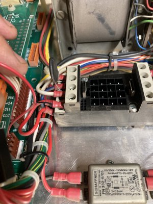
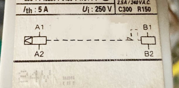
I have a old Boxford cnc lathe that I'm trying to get up and running. It will not power the spindle motor in forward, reverse works as it should. When I push the either direction button on the console I hear and see the relay flipping. I don't have a schematic and trying to understand the relay schematic. The diagram looks like there should be 3 banks of terminals ( 1 for the constant and 2 for the variable side) but it looks like there are 4 banks of terminals. I'm missing something, can anyone help? I don't have a schematic and the relay in question is a RHK412B if that helps.
-BradIMG_1221.JPGIMG_1223.JPGRHK412B.jpg
 

Attachments

  • IMG_1222.JPG
    IMG_1222.JPG
    302.2 KB · Views: 8
What diagram are you speaking of? I see the relay has 4 poles, but they may not be using all of them
Couple ways you could attack this- you could test the relay by itself on the bench with a 24 volt supply and ohmmeter.
If it checked ok that would mean there must be a bad connection, possibly at the relay socket.
You might want to check the terminals on the socket for tightness, and the wire lugs for bad crimps/corrosion

You are going to need a schematic diagram of this thing at some point- I would spend some time trying to find one
 
What diagram are you speaking of?
The diagram on the side of the relay, where it looks like terminal 11 is common and the relay goes switches between 12 to 14. I can't read the terminals if they might be numbered, maybe 4 of them are the A-1, A-2, B-1 & B-2.
 
Have you seen this website?

 
Examine the relay pins closely, they may be numbered. If not, you'll need to ID the terminals by bench testing it, unless you can
track down the data sheet online for that part
It looks like there are 4 single pole contacts- For pole #1: 11 is the common, 12= normally closed, 14= normally open. And so on
 
Last edited:
Examine the relay pins closely, they may be numbered. If not, you'll need to ID the terminals by bench testing it
I'll keep digging, I do see the terminal numbers on the ends after I moved the wires out of the way.
Can anyone decipher what is going on at terminals A-1, A-2, B-1 & B-2 by looking at the diagram. I deleted the switching parts of the diagram to make it easy to see what I'm looking at.
Can I put the relay in a ultrasonic cleaner using 100% IPA, if it turns out it is the relay?
 

Attachments

  • RHK412B Diagram.jpg
    RHK412B Diagram.jpg
    90.9 KB · Views: 8
It may be a latching relay- one coil latches it closed and the other coil unlatches
I can't advise you on the cleaning process-
 
A-1 A2 power ground switches contacts one way. B-1 B-2 power ground switches contacts the other way
 
If you look up the relays part number you will find data for it. If you don't have a schematic for the wiring then you need to look up the data for the other components.
It looks like a master stop /on relay or estop relay. but how the contacts are wired , one to drive enable power relay circuit, axis enable possible second for spindle drive enable, pneumatic/ hydraulic start?
I would look for simple things like limit switches, pressure switches, safety switches first.
 
Back
Top