Help Verify my Torque Calculations

harrzack

Harrzack
Registered
Joined
Mar 27, 2013
Messages
74
I've scoured the net and have been immersed in all sorts of formulas! This is the result of my work, and hoping there is a good engineer/machinist/math head here that can confirm (or deny) my conclusions.

I want to build an Arduino controlled stepper system to raise and lower the mill head (Sieg SX2.7/LMS 5500). I know you can buy stuff - but "just wanna do this!" :)

The work follows: (excuse any lapses of terminology...)

A milling machine has a head that is raised and lowered by a leadscrew. The leadscrew pitch is .05" i.e it moves the head .05" per revolution of the crank. The crank is attached to the leadscrew through 2 bevel gears, so there is a bit of additional built in mechanical advantage.

Empirically I've found that it takes about 4 Lbs to move the crank up a turn or two. I'm using 5lb as the load

.05" = 1.27mm or .00127 meters
5 Lb = 2.3 Kg
Force = m*a - so the force of gravity on this mass is 2.3 Kg* 9.8 m/s or about 23 Newtons.

Allow 1 second for 1 turn of the screw = 1.27mm/second

I'd like to raise the head at 10 turns/second which = 12.7mm/second.
The additional lifting force (friction and other losses aside) will be 2.3 Kg * 12.7 = 29 Newtons
23N+29N = 52 Newtons total - I'll use 60N

The stepper will have a 36 groove timing pulley with PD of 35mm or r of .0175 meters
Torque at motor shaft will be 60N * .0175 = 1.05 N/m

If I attach a 72 groove timing pulley with a PD of 69 mm I should get a 2X torque multiplication
which will give 2.1 N/m at the drive shaft.

Power needed will be 60N * .0127 m/s = .76 watts

So - Minimum requirements:
2 watt 24 VDC power supply
Any steper motor holding torque of better than 1.05 N/m.
 
I think you've made an error in your first "set" of calculations. You mention having to exert ~4 lbs to turn the crank. Instead of multiplying this by .05" (the amount the head is raised), you should multiply by the length of the crank arm to get the torque needed to turn the crank.

The mechanical advantage of the pulleys is lots simpler to calculate than you want to make it. It's a simple ratio of teeth, ie, 72:36 = 2:1. So take the torque requirement you calculate from the crank and divide by two to get the torque requirement of the motor.

Now factor in how fast you want the motor to turn (based on how fast you want to raise the head), and you should be on the way to getting the power requirement. The old classic definition is that horsepower = torque * RPM. I forget the exact fudge factors you need for the metric equivalent, but it sounds like you're at least familiar with the units.

"Back-of-the-envelope" reality check ... What really caught my eye was your final figure of 0.76 watts for the motor. It looked way too low! Assuming a 24 volt supply, that's just 32 milliamps (P=E*I; I=P/E)! A 2 watt 24 volt power supply is just 1/12 amp. If your power requirements were that low, you'd be able to run the motor with a stack of flashlight batteries :)
 
John - A huge THANKS for the review of my work! I'm especially embarrassed with my oversight of the power calcs... I do have a good electronics background and SHOULD have seen that right away. When you get 'tied to the formulas' it is easy to loose common sense.

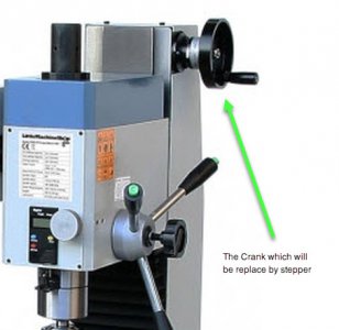
I do understand the ME provided by tooth-counts of gears - I just can't get inside the mill to see them... The head itself I estimate to be around 40 lbs, and with the combination of the leadscrew and bevel gears to turn it I just threw in the fact the there was extra 'help' inside. I understand all I need to care about is what it takes to turn the shaft the crank is attached to. I've added a detail of the crank to lift the head so you have a better idea of the project.

I will review my work and take all your points into consideration. I have looked at the steppers used in CNC work, and they seem to be around 350 in/oz with 4 or 5 amp power supplies... so that should give a good ball park.

The speed at which the head would be raised was somewhat arbitrary - I was able to crank 10 turns in about 10 secs. Later I've thought that if I'd like to move it faster I'll probably need more power and so will do a range of speeds and that will push the power & torque need up.

Back to the drawing board and calculators! ;)

MillDetail.jpg
 
Can I please have some clarification?

You say it takes about 4 lb to move the head, so you've used a nominal value of 5 lb in your calculations. That makes sense.

What I don't quite follow is where you are applying that 4 lb? Are you applying that pressure to the handle on the crankwheel in the picture?

If so, then what you need to calculate is the torque that is being applied to the shaft in the centre of said crankwheel.

For example if that is a 4" crankwheel then the torque applied to the shaft by the nominal 5 lb is going to be a function of that force and the radius of the wheel.

I'm going to switch to metric units to make the calculations easier now.

As you said, 5 lb is about 2.3 kg, which is 22.54 Newtons - round that up to 23 Newtons for a little more grunt.

In this example the distance from the handle to the centre of the shaft is 2", or 0.05 metres, so the torque required is simply 23N * 0.05m, which is 1.15Nm. (Which is 0.86 lb.ft or 163 Oz.in)

With that information in hand you can now either select a suitable stepper motor for direct drive, or keep your handwheel in place and modify your design to include manual and power feed by means of the toothed belt that you described earlier.

Either way a 1.26 Nm, NEMA 23 stepper motor can be had for well under $50 from eBay.

Adjust as necessary for your dimensions.

Cheers,...Jon.


Sent from my Lenovo YT3-X50F using Tapatalk
 
Greeting Jon! Yes I'm beginning to see what you say. The first reply from John got me back to review my calcs and I found the error of my ways.

In redoing my work I pretty much got what you are showing. One big mistake was that I didn't convert 5 lb to 22 Newtons - Just not used to thinking that way.
I don't want to do a direct drive, so will be using timing belt pulleys. I want to use a 2:1 to get a "little more grunt" as you say :)
The motor pulley (36T) will have a PD of 35mm, r=17.5mm or .018 meters. The driven pulley (72T) will have a PD of 69mm, r=35mm or .035 meters.

In the example I studied, the added effect of gravity for the total mass that was being moved. (N*9.8m/sec). Since this load is being held by the leadscrew can that ignored?
I guess so since I CAN turn the crank with about 5 lbs force!! DUH!

So with the lighter mass of 23N, the driven pulley will need 23*.035m or .8 N/m - and the motor will need to provide only 1/2 of that. Which is close to where you are but with the pulley PD's making a slight diff.

There is also the issue of how fast I want to raise or lower the head. The leadscrew pitch is .05" or .00127m. 10 turns of the leadscrew being driven will raise the head .0127 meters, and so on.

10 revs/sec of driven pulley = a movement of .0127m/s (.5"/sec). 10 RPS = 60 RPM at the driven pulley and 120 at the motor.
23N *.0127m/s = .29 N/m - which I also understand is the power needed. As it goes faster, the power needs go up - but now I have to check the torque curves of the steppers to see how speed will affect things.

So as you say - a (about) 1Nm stepper (along my 2:1 pulleys) should do the job - with a slightly larger one if the 'need for speed' dictates!

Thanks for you thoughts!

=Alan R
 
10 revs/sec of driven pulley = a movement of .0127m/s (.5"/sec). 10 RPS = 60 RPM at the driven pulley and 120 at the motor.
10 rps = 600 rpm

Tom
 
I've scoured the net and have been immersed in all sorts of formulas! This is the result of my work, and hoping there is a good engineer/machinist/math head here that can confirm (or deny) my conclusions. ........

Rather than go through all of the gyrations in treating the lead screw as a ramp, pulley ratios, etc., I have used the conservation of energy to calculate necessary torque. Energy equals work done and energy is conserved (frictional losses disregarded).

If you lift 5 lbs of weight over a distance of 10 inches, you have done 50 in.lbs. of work. If you are turning a crank with a length of 5"and you will turn the crank 1.5 turns to raise the weight 1 inch, you have traveled a distance of 1.5 x 2 x π x5 (angle in radians x radius) or 47.12 in.. The force required at the crank to perform this work will be 1.06 lbs.

Since torque is equal to the force x the crank length, the torque would be 5.3 lb-in. There will be frictional losses, particularly with a lead screw as opposed to a ball screw so doubling or tripling the torque value should be a good safety factor.

Another way to determine the torque requirements is to simply measure the force required to lift the head. A spring scale or digital scale attached to the crank handle so that it pulls at a right angle to to a line between the crank and the axle will determine the re1quired force and a measure of the crank length is the other number. The required force x the crank length is the required torque. In your case, you measured 4 lbs of force and the crank length is 5 in., your required torque is 20 in. lbs. or 320 oz. in.. Again, allow a safety factor of perhaps 50% for something like 480 oz.-in. of torque required.
 
RJ - thanks for another view. I actually did put a weight on the crank handle - 4Lb -
And it raised the head. Then I took a digital postal scale and pressed up on the crank and got the same thing. All in all it looks like a 320 in/oz may do the job. Might not get a wide speed range, but will be easier than hand ranking. If I have enough power I might even be able to cut with a " power down feed" .
 
Back
Top