- Joined
- May 7, 2014
- Messages
- 776
Hi everyone and good evening. Before I take the plunge on the AjaxCNC setup - I have been in contact w/ one of the original developers of the Dynetics/Bandit controller. Name is Len and a GREAT guy. He thinks this thing is really close and just needs a little push on the Drive connections for the MSI>>> But this stuff is all soooooo OLD!
thought I'd punt and see if I can pull a 'seahawks' TD here.
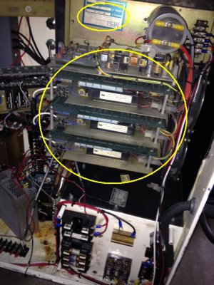
This Mill has been sort of setup w/ the parts -But not all the connections. the MSI MM3-CCC-09 is listed as both a server drive and amp. Are these the same thing?
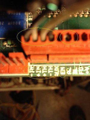
Also - The inputs from the Bandit3 need to go to the amp/drive. All I see on the MSI board for inputs is show in the pics below. +IN -IN +TH -TH and EN in yellow below.
So Here goes:
A) I have 6 sets of wires. 2 sets of X, Y, Z. Total 6 sets.
B) 1 set comes from the Bandit3's "Channel 0, 1, and 2. I've ohmed them back to that. TWO Wires. A black and a white.
C) From the DC motor cables, thru the *conduit and into the cabinet- is the 2nd set. There is a Blue, White, and Black in each bundle. The bundles are labled X, Y, Z.
* I will pull the molex circle conn off and ohm these back to the X motor I've yanked apart tomorrow.
Somehow this just needs to be connected together and I think I could try to power everything up? Just not sure what goes into the MSI amp/drive connectors +/-IN and +/-TH and EN locations. That's 5 wire spots. I have 5 wires per set of X,Y, Z. and five signal spots on the MSI for each X,Y,Z ????? is that a BIG leap???
I belive someone started to upgrade this unit some time ago and simply did not complete (obviously) the DC motor to Amp/Driver setups. Not even sure all the right gear is there technically.


Last edited:
